


Chapter 1 Getting Started
ViewStation User Guide 8 www.polycom.com
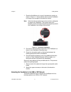
LED Activity on the V.35 Network Interface Module
The LEDs on the front of the V.35 network interface module indicate
the connection status to the ViewStation.
When the ViewStation is powered on, the following light sequence
occurs:
1. Both LEDs flash once to indicate that the LED is working
properly.
2. The bottom amber LED glows solid to indicate that the
ViewStation is communicating with the network interface
module.
3. The top green LED glows solid to indicate that the ViewStation
is communicating with the network.
The top green LED corresponds to port status, and the bottom
amber LED corresponds to DCE clock status.
Once the interface is properly connected, the ViewStation H.323
with V.35 is ready to be configured for Ethernet LAN connectivity.
Connecting the ViewStation to an Ethernet LAN
All ViewStation models use the same configuration type for
connecting the ViewStation to an Ethernet LAN. Complete the
following steps to connect the ViewStation to an Ethernet LAN:
1. Connect the orange-tipped RJ-45 cable to the orange RJ-45
port labeled LAN on the back of the ViewStation H.323.
2. Connect the opposite end of the orange-tipped RJ-45 cable to
an Ethernet LAN wall jack.
3. A green light appears on the orange RJ-45 port on the back of
the ViewStation if the LAN wall jack is active.