


R0E530640MCU00 User’s Manual 5. Debugging Functions
REJ10J1733-0100 Rev.1.00 Apr. 01, 2008
Page 121 of 229
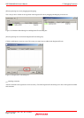
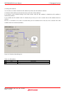
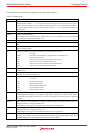
The following items of information are displayed. (This applies for bus display.)
Table 5.13 Display items
Column Description
Cycle Cycle numbers stored in trace memory. The last cycle acquired is numbered 0, and the older cycles are
assigned smaller numbers –1, –2, etc. sequentially retracing the past. If a delay count is set, the cycle in
which a trace stop condition is met is numbered 0 and the cycles that were executed until the condition is
met (cycles during a delay period) are assigned larger numbers +1, +2, etc. sequentially toward the last
cycle acquired.
Label Labels corresponding to addresses (displayed only when labels are set).
Address Addresses of the address bus.
[CAUTION] When using 4M mode, the address b31 will be “1b” when bank 0-6 is accessed. b30-28
shows the bank being accessed when b31 is “1b”.
Data Data of the data bus. Displayed in hexadecimal.
BUS Shows the external data bus width, indicated as “8b” when the bus is 8 bits wide or “16b” when 16 bits
wide.
BHE Shows the state (0 or 1) of BHE (Byte High Enable) signal. When this signal is ‘0,’ it means that an odd
address is being accessed.
BIU Shows the state between the BIU (Bus Interface Unit) and the memory and I/O.
- No change
DMA Data access such as DMA, etc. requested from other than the CPU
INT INTACK sequence start
IB Instruction code read (in bytes) requested from the CPU
DB Data access (in bytes) requested from the CPU
IW Instruction code read (in words) requested from the CPU
DW Data access (in words) requested from the CPU
R/W Shows the data bus state, indicated as “R” when in a read state, “W” when in a write state or “–” when no
accesses made.
RWT The signal indicating the valid position of bus cycle. When valid, this signal is ‘0.’ The Address, Data and
BIU lines are valid when this signal is ‘0.’
CPU Shows the state between the CPU and the BIU (Bus Interface Unit).
- No change
CB Op-code read (in bytes)
RB Operand read (in bytes)
QC Instruction queue buffer clear
CW Op-code read (in words)
RW Operand read (in words)
QN Shows the number of bytes stored in the instruction queue buffer. Displayed in the range from 0 to 4.
[CAUTION] When stopping the user program by using software break, QN (the number of bytes stored in
the instruction queue buffer) from the next cycle after an occurrence of software break is not displayed
correctly.
BUSACC When memory access is performed by a debugger operation during user program execution, shows “0”
during the emulator is occupying the MCU bus.
[CAUTION] The user program is suspended during memory access is performed.
Debug When memory access is performed by a debugger operation during user program execution, shows “0”
during the emulator is occupying the MCU bus.
[CAUTION] The user program is suspended during memory access is performed.
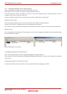
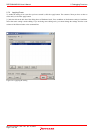
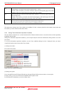
EV The event No. when a set event occurred.
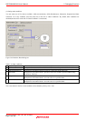
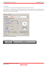
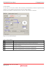
To show EV column, you need to select the EV number on the Option page of the Trace
conditions dialog box displayed from the menu of the Trace window.