


R0E530640MCU00 User’s Manual 7. Hardware Specifications
REJ10J1733-0100 Rev.1.00 Apr. 01, 2008
Page 217 of 229
7.2 Differences between the Actual MCU and Emulator
Differences between the actual MCU and emulator are shown below. When debugging the MCU using this product, be careful
about the following precautions.
IMPORTANT
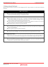
Note on Differences between the Actual MCU and Emulator:
z Operations of the emulator system differ from those of actual MCUs as listed below.
(1) Reset condition
Set the time for starting up (0.2 Vcc to 0.8 Vcc) 1 μs or less.
(2) Initial values of internal resource data of an MCU at power-on
(3) Interrupt stack pointer (ISP) after a reset is released
(4) Capacities of the internal memories (ROM and RAM)
The evaluation MCU of this product has RAM of 31 KB (00400h--07FFFh) and flash ROM of 8 KB
(0E000h--0FFFFh), 16 KB (10000h--13FFFh) and 512 KB (80000h--FFFFFh).
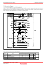
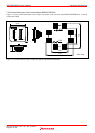
(5) Oscillator circuit
In the oscillator circuit where an oscillator is connected between pins X
IN
and X
OUT
, oscillation does not
occur because a converter board is used between the evaluation MCU and the user system. It is the same
for pins X
CIN
and X
COUT
.
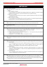
(6) A/D conversion
The characteristics of the A/D converter differ from those of actual MCU because there are a converter
board and other devices between the evaluation MCU and the user system.
Note on RESET# Input:
z A low input to pin RESET# from the user system is accepted only when a user program is being executed (only
while the RUN status LED on the E100 upper panel is lit).
Note on Voltage Detect Circuit:
z This product differs from the actual MCU because there is a pitch converter board, etc. between the evaluation
ECU and user system. Final evaluation of the voltage detect circuit (voltage down detect interrupt, voltage down
detect reset, etc.) should be executed with the actual MCU.
Notes on Maskable Interrupts:
z Even if a user program is not being executed (including when run-time debugging is being performed), the
evaluation MCU executes a debug control program. Therefore, timers and other components do not stop
running. If a maskable interrupt is requested when the user program is not being executed (including when run-
time debugging is being performed), the maskable interrupt request cannot be accepted, because the emulator
disables interrupts. The interrupt request is accepted immediately after the user program execution is started.
z Take note that when the user program is not being executed (including when run-time debugging is being
performed), a peripheral I/O interruption is not accepted.
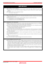
Note on DMA Transfer:
z With this product, the user program is stopped with a loop program to a specific address. Therefore, if a DMA
request is generated by a timer or other source while the user program is stopped, DMA transfer is executed.
However, make note of the fact that DMA transfer while the program is stopped may not be performed
correctly. Also note that the below registers have been changed to generate DMA transfer as explained here
even when the user program is stopped.
(1) DMA0 transfer count register TCR0 (2) DMA1 transfer count register TCR1
(3) DMA2 transfer count register TCR2 (4) DMA3 transfer count register TCR3
Note on Final Evaluation:
z Be sure to evaluate your system with an evaluation MCU. Before starting mask production, evaluate your
system and make final confirmation with a CS (Commercial Sample) version MCU.