


R0E530640MCU00 User’s Manual 1. Outline
REJ10J1733-0100 Rev.1.00 Apr. 01, 2008
Page 18 of 229
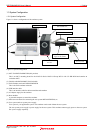
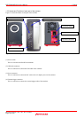
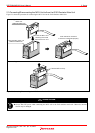
1.3.2 Names and Functions of each part of the emulator
Figure 1.2 shows the names of each part of the emulator.
(1) Power switch
(2) USB cable connector
(3) Power connector
(4) External trigger connector(5) System status LEDs
(6) Target status LEDs
Figure 1.2 Names of each part of the emulator
(1) Power switch
This is a switch to turn ON/OFF the emulator.
(2) USB cable connector
This is a connector to connect the USB cable of the emulator.
(3) Power connector
This is a connector to connect the DC cable of the AC adapter power of the emulator.
(4) External trigger connector
This is a connector to connect the external trigger cable of the emulator.