


R0E530640MCU00 User’s Manual 6. Troubleshooting (Action on Error)
REJ10J1733-0100 Rev.1.00 Apr. 01, 2008
Page 214 of 229
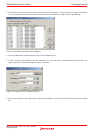
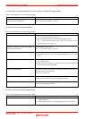
(2) Configuration Properties Dialog Box Does Not Appear at Emulator Debugger Startup
Table 6.2 Checkpoints of errors at debugger startup 1
Error Checkpoint
Communication error occurred.
Data was not sent to the target.
Check all emulator debugger settings and interface cable settings.
See “
4. Preparing to Debug” (page 67).
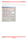
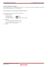
(3) Errors Occur at Connecting Dialog Box
Table 6.3 Checkpoints of errors at debugger startup 2
Error Checkpoint
User system cannot be properly built. (1) Download the proper firmware.
See“
4. Preparing to Debug” (page 67).
(2) Recheck the connection between the E100 and this product.
See “
2.3 Connecting/Disconnecting the MCU Unit to/from the E100
Emulator Main Unit” (page
25).
Emulator’s version is not the same version as
the firmware in the target.
Download the proper firmware.
See “
4. Preparing to Debug” (page 67).
Target MCU is in the reset state. (1) Check the reset pin of the user system is pulled up.
(2) Check the reset pin of the user system has changed from "L" to "H"
level.
Target MCU cannot be reset. (1) If the reset circuit of the user system has a watchdog timer, disable
the watchdog timer.
(2) Check that power is properly supplied to the user system and that the
user system is properly grounded.
Target is in "HOLD" state. The MCU is either in stop mode or wait mode. Either reset the MCU or
cancel the mode with an interrupt.
See MCU specifications.
Target clock is stopped. When the clock is supplied from an external oscillator, check that the
oscillator circuit in the user system is oscillating properly.
Target MCU is not receiving power. Check that power is properly supplied to the user system and that the
user system is properly grounded.
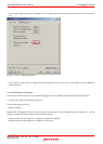
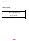
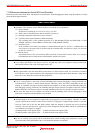
(4) Errors Occur at Emulator Debugger Startup
Table 6.4 Checkpoints of errors at debugger startup 3
Error Checkpoint
Target MCU is uncontrollable. (1) Check that the NQPACK etc. mounted on the user system is
soldered properly.
(2) Check that the connector is installed properly to the user system.