


R0E530640MCU00 User’s Manual 7. Hardware Specifications
REJ10J1733-0100 Rev.1.00 Apr. 01, 2008
Page 218 of 229
7.3 Connection Diagram
7.3.1 Connection Diagram for the R0E530640MCU00
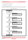
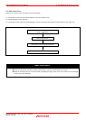
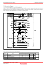
Figure 7.1 shows a connection diagram of the R0E530640MCU00. This connection diagram mainly shows the circuit to be
connected to the user system. The circuits not connected to the user system such as the emulator’s control system are omitted.
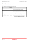
Table 7.2 shows IC electric characteristics of this product for reference purpose.
Figure 7.1 Connection diagram
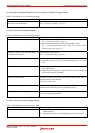
Table 7.2 Electrical characteristics of the 74HC4066
Condition Standard values
Symbol Item
Vcc
Min. Standard Max.
Unit
RON ON resistor
4.5V - 96 170
ΔRON ON resistor difference
4.5V - 10 -
Ω
IOFF Leak current (Off)
12.0V - - ±100
IIZ Leak current (On, output: open) 12.0V - - ±100
nA