


www.ti.com
2.12VTPIOBufferCalibration
2.13Auto-InitializationSequence
PeripheralArchitecture
TheDDR2memorycontrollerisabletocontroltheimpedanceoftheoutputIO.Thisfeatureallowsthe
DDR2memorycontrollertotunetheoutputimpedanceoftheIOtomatchthatofthePCBboard.Control
oftheoutputimpedanceoftheIOisanimportantfeaturebecauseimpedancematchingreduces
reflections,creatingacleanerboarddesign.CalibratingtheoutputimpedanceoftheIOwillalsoreduce
thepowerconsumptionoftheDDR2memorycontroller.Thecalibrationisperformedwithrespectto
voltage,temperature,andprocess(VTP).TheVTPinformationobtainedfromthecalibrationisusedto
controltheoutputimpedanceoftheIO.
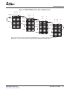
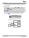
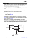
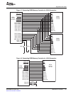
TheimpedanceoftheoutputIOisselectedbythevalueofresistorsconnectedtotheDDR_ZNand
DDR_ZPpins.Theresistorshouldbechosentobe4timesthedesiredimpedanceoftheoutputIO.The
DDR2referencedesignrequirestheresistorvaluestobe200ohms.ThismeansthatboththeDDR_ZN
andDDR_ZPpinsmusthavea200ohmresistorconnectedtothem.Figure3describesproper
connectionoftheDDR_ZNandDDR_ZPpins.
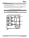
TosettheoutputimpedanceoftheIO,calibrationmustbeinitiatedbywritingtothefollowing
memory-mappedregisters:
•VTPIOControlRegister(VTPIOCR)
•DDRVTPRegister(DDRVTPR)
•DDRVTPEnableRegister(DDRVTPER)
TheVTPIOcontrolregisteriswrittentobeginthecalibration.Oncethecalibrationiscomplete,theVTP
informationisstoredintheDDRVTPregister.TheDDRVTPregistershouldthenberead,retrievingthe
VTPinformation,andtheVTPinformationwrittentotheVTPIOcontrolregister.TheDDRVTPenable
registeriswrittentoenable/disableaccesstotheDDRVTPregister.Steps8-15oftheinitialization
proceduredescribedinSection2.13.2showstheprocedurethatmustbefollowedtoperformVTPIO
calibration.
Note:VTPIOcalibrationmustbeperformedfollowingdevicepowerupanddevicereset.Ifthe
DDR2memorycontrollerisresetviathePowerandSleepController(PSC)andtheVTP
inputclockisdisabled,accessestotheDDR2memorycontrollerwillnotcomplete.To
re-enableaccessestotheDDR2memorycontroller,enabletheVTPinputclockandthen
performtheVTPcalibrationsequenceagain.
TheDDR2SDRAMcontainsmodeandextendedmoderegistersthatconfiguretheDDR2memoryfor
operation.Theseregisterscontrolbursttype,burstlength,CASlatency,DLLenable/disable(ontheDDR2
device),single-endedstrobe,etc.TheDDR2memorycontrollerprogramsthemodeandextendedmode
registersoftheDDR2memorybyissuingMRSandEMRScommandsduringtheinitializationsequence.
TheinitializationsequenceperformedbytheDDR2memorycontrolleriscompliantwiththeJESDEC79-2A
specification.TheDDR2memorycontrollerperformsaninitializationsequenceunderthefollowing
conditions:
•Followingreset(risingedgeofVRSTorVCTL_RST)
•FollowingawritetotheDDRDRIVEbitfieldorthetwoleast-significantbytesintheSDRAMbank
configurationregister(SDBCR)
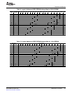
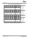
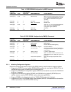
Duringtheinitializationsequence,theDDR2memorycontrollerissuesMRSandEMRScommandsthat
configuretheDDR2SDRAMmoderegisterandextendedmoderegister1withthevaluesdescribedin
Table14andTable15.TheDDR2SDRAMextendedmoderegisters2and3areconfiguredwithavalue
of0h.Attheendoftheinitializationsequence,theDDR2memorycontrollerperformsanautorefresh
cycle,leavingtheDDR2memorycontrollerinanidlestatewithallbanksdeactivated.
Whenaresetoccurs,theDDR2memorycontrollerimmediatelybeginstheinitializationsequence.Under
thiscondition,commandsanddatastoredintheDDR2memorycontrollerFIFOswillbelost.However,
whentheinitializationsequenceisinitiatedbyawritetothetwoleast-significantbytesinSDBCR,data
andcommandsstoredintheDDR2memorycontrollerFIFOswillnotbelostandtheDDR2memory
controllerwillensurereadandwritecommandsarecompletedbeforestartingtheinitializationsequence.
SPRU986B–November2007DDR2MemoryController31
SubmitDocumentationFeedback