


User's Guide
Control Panel 4-39
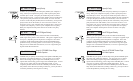
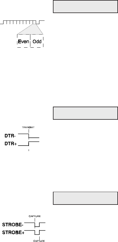
Specify Parity
PARITY lets you tell the printer what parity method your computer is
using. When your computer uses parity, it adds a special parity bit to
each data byte it sends. This parity bit enables the printer to detect a
data transmission error. In the even parity method, the sum of the binary
1 bits plus the parity bit must be an even number, or else an error has
occurred. In the odd parity method, the sum of the binary 1 bits plus the
parity bit must be an odd number, or else an error has occurred. You
must select None if your computer does not support parity; Odd if your
computer uses odd parity; or Even if your computer uses even parity.
Both your computer and the printer must be set for the same parity
method.
48) PARITY: None
Set DTR Signal Polarity
DTR lets you specify the polarity of the extra Data Terminal Ready
(DTR) signal in the printer's serial interface. The signal is supplied on pin
25 or pin 11, depending on how the printer is configured. Since most
computers use the standard DTR signal on pin 20 for handshaking, this
parameter set-ting is usually ignored. You can select Neg for a signal
that goes low to enable data transmission; or Pos for a signal that goes
high to enable data transmission.
Specify STROBE Pulse Edge
for Data Capture
STROBE lets you specify on which edge of the parallel STROBE pulse
the printer will capture the data byte. You can select Neg to capture
data on the leading, negative edge of the STROBE pulse; or Pos to
capture data on the trailing, positive edge of the STROBE pulse. In most
cases, the Neg setting will provide reliable data transfer. If your
computer's parallel interface sends the STROBE pulse before data has
fully settled on the data lines (resulting in data loss), you may be able to
correct the problem by selecting the Pos setting.
49) DTR: Pos
50) STROBE: Neg
User's Guide
Control Panel 4-39
Specify Parity
PARITY lets you tell the printer what parity method your computer is
using. When your computer uses parity, it adds a special parity bit to
each data byte it sends. This parity bit enables the printer to detect a
data transmission error. In the even parity method, the sum of the binary
1 bits plus the parity bit must be an even number, or else an error has
occurred. In the odd parity method, the sum of the binary 1 bits plus the
parity bit must be an odd number, or else an error has occurred. You
must select None if your computer does not support parity; Odd if your
computer uses odd parity; or Even if your computer uses even parity.
Both your computer and the printer must be set for the same parity
method.
48) PARITY: None
Set DTR Signal Polarity
DTR lets you specify the polarity of the extra Data Terminal Ready
(DTR) signal in the printer's serial interface. The signal is supplied on pin
25 or pin 11, depending on how the printer is configured. Since most
computers use the standard DTR signal on pin 20 for handshaking, this
parameter set-ting is usually ignored. You can select Neg for a signal
that goes low to enable data transmission; or Pos for a signal that goes
high to enable data transmission.
Specify STROBE Pulse Edge
for Data Capture
STROBE lets you specify on which edge of the parallel STROBE pulse
the printer will capture the data byte. You can select Neg to capture
data on the leading, negative edge of the STROBE pulse; or Pos to
capture data on the trailing, positive edge of the STROBE pulse. In most
cases, the Neg setting will provide reliable data transfer. If your
computer's parallel interface sends the STROBE pulse before data has
fully settled on the data lines (resulting in data loss), you may be able to
correct the problem by selecting the Pos setting.
49) DTR: Pos
50) STROBE: Neg