


User's Guide
Set Up 2-11
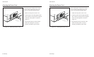
Attaching the Interface Cable
The printer has a Centronics
®
-compatible
parallel interface and an EIA RS-232-C-
compatible serial interface for communica-
tions with computers.
The printer does not come with an interface
cable, since the correct cable to use
depends on your computer. If you do not
already have an interface cable, you can
obtain one at a local computer supply store.
If you are going to use the parallel inter-
face, the cable must have a 36-pin male
Centronics-type connector on the printer
end. If you are going to use the serial
interface, the cable must have a 25-pin
male DB-25 connector on the printer end.
The Interfaces appendix provides more
details.
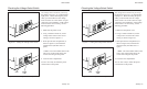
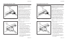
To connect an interface cable, use the
following procedure:
1. Make sure that both your computer and
printer are turned off.
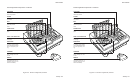
2. If you are going to use the parallel
interface, plug a parallel cable into the
parallel receptacle (see figure 2-13)
and lock it into place with the wire
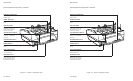
locking loops. If you are going to use
the serial interface, plug a serial cable
into the serial receptacle (see figure
2-14) and use a small slotted screw-
driver to tighten the screws that secure
the cable to the printer.
3. Connect the other end of the interface
cable to the appropriate connector on
your computer.
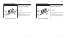
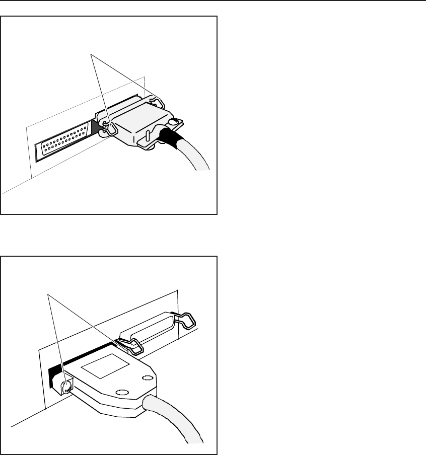
Figure 2-13. Connecting the Parallel Cable
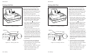
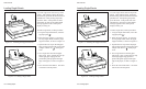
Figure 2-14. Connecting the Serial Cable
SCREWS
WIRE LOCKING
LOOPS
User's Guide
Set Up 2-11
Attaching the Interface Cable
The printer has a Centronics
®
-compatible
parallel interface and an EIA RS-232-C-
compatible serial interface for communica-
tions with computers.
The printer does not come with an interface
cable, since the correct cable to use
depends on your computer. If you do not
already have an interface cable, you can
obtain one at a local computer supply store.
If you are going to use the parallel inter-
face, the cable must have a 36-pin male
Centronics-type connector on the printer
end. If you are going to use the serial
interface, the cable must have a 25-pin
male DB-25 connector on the printer end.
The Interfaces appendix provides more
details.
To connect an interface cable, use the
following procedure:
1. Make sure that both your computer and
printer are turned off.
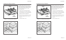
2. If you are going to use the parallel
interface, plug a parallel cable into the
parallel receptacle (see figure 2-13)
and lock it into place with the wire
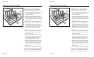
locking loops. If you are going to use
the serial interface, plug a serial cable
into the serial receptacle (see figure
2-14) and use a small slotted screw-
driver to tighten the screws that secure
the cable to the printer.
3. Connect the other end of the interface
cable to the appropriate connector on
your computer.
Figure 2-13. Connecting the Parallel Cable
Figure 2-14. Connecting the Serial Cable
SCREWS
WIRE LOCKING
LOOPS