


User's Guide
C-10 Interfaces
Data Terminal Ready
The Data Terminal Ready (DTR) signal indicates when DTE must stop
sending data and when it should continue. This stopping and starting
(called handshaking) is necessary to prevent DCE's input buffer from
overflowing. If DTR is high, DTE may send data; if DTR is low, DTE
must pause.
Inverted Data Terminal Ready
The Inverted Data Terminal Ready (DTR–) signal is the same as DTR,
except the polarity of the signal is reversed.
Chassis and Signal Grounds
Chassis Ground (CGND) and Signal Ground (SGND) provide the neces-
sary grounding.
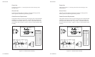
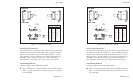
Cable/Connector Requirements
The serial connecter must have a 25-pin male plug (Amphenol 177-RRB-
25P D-SUB or equivalent). The backshell must be metal (Amphenol 17-
1630-25 or equivalent). The cable must be shielded with twisted pair
leads (Beldon 9505 or equivalent). The serial cable must not exceed 50
feet (15.25 meters). Figure C-4 shows a typical serial cable assembly.
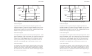
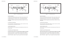
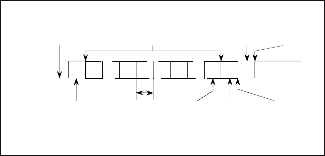
Figure C-3. Serial Data Format
LSB
00
MSB
07
01 0605040302
ONE BIT
TIME
(ONE
BAUD
RATE)
START
BIT
RETURN
TO IDLE
STATE OF
LINE
OPTIONAL
PARITY
BIT
OPTIONAL
8
TH
BIT
STOP
BIT7 OR 8 DATA BITS
START BIT
OF NEXT
CHARACTER
LOW (-)
HIGH (+)
IDLE STATE
OF LINE
User's Guide
C-10 Interfaces
Data Terminal Ready
The Data Terminal Ready (DTR) signal indicates when DTE must stop
sending data and when it should continue. This stopping and starting
(called handshaking) is necessary to prevent DCE's input buffer from
overflowing. If DTR is high, DTE may send data; if DTR is low, DTE
must pause.
Inverted Data Terminal Ready
The Inverted Data Terminal Ready (DTR–) signal is the same as DTR,
except the polarity of the signal is reversed.
Chassis and Signal Grounds
Chassis Ground (CGND) and Signal Ground (SGND) provide the neces-
sary grounding.
Cable/Connector Requirements
The serial connecter must have a 25-pin male plug (Amphenol 177-RRB-
25P D-SUB or equivalent). The backshell must be metal (Amphenol 17-
1630-25 or equivalent). The cable must be shielded with twisted pair
leads (Beldon 9505 or equivalent). The serial cable must not exceed 50
feet (15.25 meters). Figure C-4 shows a typical serial cable assembly.
Figure C-3. Serial Data Format
LSB
00
MSB
07
01 0605040302
ONE BIT
TIME
(ONE
BAUD
RATE)
START
BIT
RETURN
TO IDLE
STATE OF
LINE
OPTIONAL
PARITY
BIT
OPTIONAL
8
TH
BIT
STOP
BIT7 OR 8 DATA BITS
START BIT
OF NEXT
CHARACTER
LOW (-)
HIGH (+)
IDLE STATE
OF LINE