


User's Guide
C-2 Interfaces
Signals and Timing
The parallel interface consists of a data clock signal, eight data bit signals,
two handshaking signals, two printer error signals, two printer control
signals, two printer select signals, a power line, fifteen ground lines, and
three lines that are not connected.
Data Transfer Signals
The primary function of the interface is to transfer data from the compu-
ter to the printer. This function requires eleven signals. To transfer each
data byte from the computer to the printer, the following signals are sent:
99
99
9 During normal operation, the computer monitors a BUSY signal
from the printer. When BUSY goes low, the printer is ready to
receive a data byte.
99
99
9 When BUSY is low, the computer simultaneously represents the
eight bits of the data byte on eight data lines––DB1 through DB8.
The least significant bit (LSB) is represented on DB1, the next bit
on DB2, and so on. If the bit is logical "0", the signal is low. If the
bit is logical "1", the signal is high.
99
99
9 After waiting at least 0.5 microsecond, the computer pulses a
STROBE- signal for at least 0.5 microsecond to tell the printer
that data is present on the data lines. The computer continues to
hold the data on the data lines for at least 0.5 microsecond after
the STROBE- pulse.
99
99
9 Within 0.25 microsecond after the leading edge of the STROBE-
pulse, the printer changes the BUSY signal to high to indicate that
it is busy.
99
99
9 During the next 5 microseconds (or more), the printer reads the
data lines and transfers the byte to printer memory.
99
99
9 When ready to receive another byte, the printer sets the BUSY
signal back to low and pulses an ACK- signal low for at least 4
microseconds.
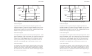
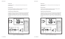
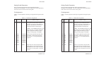
The timing of each event is critical. Figure C-1 shows the parallel data
transfer timing diagram.
User's Guide
C-2 Interfaces
Signals and Timing
The parallel interface consists of a data clock signal, eight data bit signals,
two handshaking signals, two printer error signals, two printer control
signals, two printer select signals, a power line, fifteen ground lines, and
three lines that are not connected.
Data Transfer Signals
The primary function of the interface is to transfer data from the compu-
ter to the printer. This function requires eleven signals. To transfer each
data byte from the computer to the printer, the following signals are sent:
99
99
9 During normal operation, the computer monitors a BUSY signal
from the printer. When BUSY goes low, the printer is ready to
receive a data byte.
99
99
9 When BUSY is low, the computer simultaneously represents the
eight bits of the data byte on eight data lines––DB1 through DB8.
The least significant bit (LSB) is represented on DB1, the next bit
on DB2, and so on. If the bit is logical "0", the signal is low. If the
bit is logical "1", the signal is high.
99
99
9 After waiting at least 0.5 microsecond, the computer pulses a
STROBE- signal for at least 0.5 microsecond to tell the printer
that data is present on the data lines. The computer continues to
hold the data on the data lines for at least 0.5 microsecond after
the STROBE- pulse.
99
99
9 Within 0.25 microsecond after the leading edge of the STROBE-
pulse, the printer changes the BUSY signal to high to indicate that
it is busy.
99
99
9 During the next 5 microseconds (or more), the printer reads the
data lines and transfers the byte to printer memory.
99
99
9 When ready to receive another byte, the printer sets the BUSY
signal back to low and pulses an ACK- signal low for at least 4
microseconds.
The timing of each event is critical. Figure C-1 shows the parallel data
transfer timing diagram.