


BLADEOS 6.5.2 Application Guide
BMD00220, October 2010 Chapter 8: Spanning Tree Protocols 115
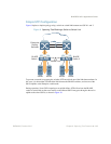
Simple STP Configuration
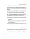
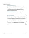
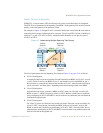
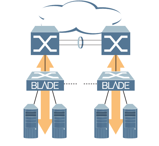
Figure 9 depicts a simple topology using a switch-to-switch link between two G8124 1 and 2.
Figure 9 Spanning Tree Blocking a Switch-to-Switch Link
To prevent a network loop among the switches, STP must block one of the links between them. In
this case, it is desired that STP block the link between the BLADE switches, and not one of the
G8124 uplinks or the Enterprise switch trunk.
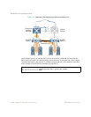
During operation, if one G8124 experiences an uplink failure, STP will activate the BLADE
switch-to-switch link so that server traffic on the affected G8124 may pass through to the active
uplink on the other G8124, as shown in Figure 10.
Enterprise
Routing
Switches
x
Server Server Server Server
BLADE
Switch 1
BLADE
Switch 2
STP
Blocks Link