


BLADEOS 6.5.2 Application Guide
320 Chapter 22: Basic Redundancy BMD00220, October 2010
Active MultiPath Protocol
Active MultiPath Protocol (AMP) allows you to connect three switches in a loop topology, and
load-balance traffic across all uplinks (no blocking). When an AMP link fails, upstream
communication continues over the remaining AMP link. Once the failed AMP link re-establishes
connectivity, communication resumes to its original flow pattern.
AMP is supported over Layer 2 only. Layer 3 routing is not supported. Spanning Tree is not
required in an AMP Layer 2 domain. STP BPDUs will not be forwarded over the AMP links, and
any BPDU packets received on AMP links are dropped.
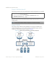
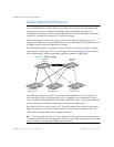
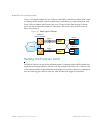
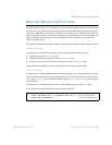
Each AMP group contains two aggregator switches and one access switch. Aggregator switches
support up to 22 AMP groups. Access switches support only one AMP group. Figure 40 shows a
typical AMP topology, with two aggregators supporting a number of AMP groups.
Figure 40 AMP Topology
Each AMP group requires two links on each switch. Each AMP link consists of a single port, a
static trunk group, or an LACP trunk group. Local non-AMP ports can communicate via local
Layer 2 switching without passing traffic through the AMP links. No two switches in the AMP loop
can have another active connection between them through a non-AMP switch.
Each AMP switch has a priority value (1-255). The switch with the lowest priority value has the
highest precedence over the other switches. If there is a conflict between switch priorities, the
switch with lowest MAC address has the highest precedence.
Note – For proper AMP operation, all access switches should be configured with a higher priority
value (lower precedence) than the aggregators. Otherwise, some AMP control packets may be sent
to access switches, even when their AMP groups are disabled.
Aggregator
Switch
Access Switch
(AMP Group 1)
Aggregator
Switch
Access Switch
(AMP Group 2)
Access Switch
(AMP Group 3)