


BLADEOS 6.5.2 Application Guide
BMD00220, October 2010 Chapter 20: OSPF 291
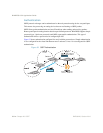
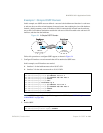
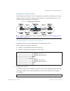
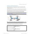
Example 2: Virtual Links
In the example shown in Figure 35, area 2 is not physically connected to the backbone as is usually
required. Instead, area 2 will be connected to the backbone via a virtual link through area 1. The
virtual link must be configured at each endpoint.
Figure 35 Configuring a Virtual Link
Note – OSPFv2 supports IPv4 only. IPv6 is supported in OSPFv3 (see “OSPFv3 Implementation
in BLADEOS” on page 298).
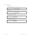
Configuring OSPF for a Virtual Link on Switch #1
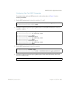
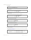
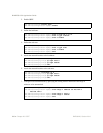
1. Configure IP interfaces on each network that will be attached to the switch.
In this example, two IP interfaces are needed:
Interface 1 for the backbone network on 10.10.7.0/24
Interface 2 for the transit area network on 10.10.12.0/24
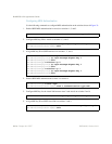
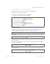
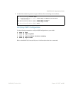
2. Configure the router ID.
A router ID is required when configuring virtual links. Later, when configuring the other end of the
virtual link on Switch 2, the router ID specified here will be used as the target virtual neighbor
(nbr) address.
Switch 2
Switch 2
Switch 1
Switch 1
RS G8124(config)# interface ip 1
RS G8124(config-ip-if)# ip address 10.10.7.1
RS G8124(config-ip-if)# ip netmask 255.255.255.0
RS G8124(config-ip-if)# enable
RS G8124(config-ip-if)# exit
RS G8124(config)# interface ip 2
RS G8124(config-ip-if)# ip address 10.10.12.1
RS G8124(config-ip-if)# ip netmask 255.255.255.0
RS G8124(config-ip-if)# enable
RS G8124(config-ip-if)# exit
RS G8124(config)
# ip router-id 10.10.10.1