


BLADEOS 6.5.2 Application Guide
338 Chapter 24: Virtual Router Redundancy Protocol BMD00220, October 2010
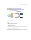
High Availability Configurations
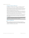
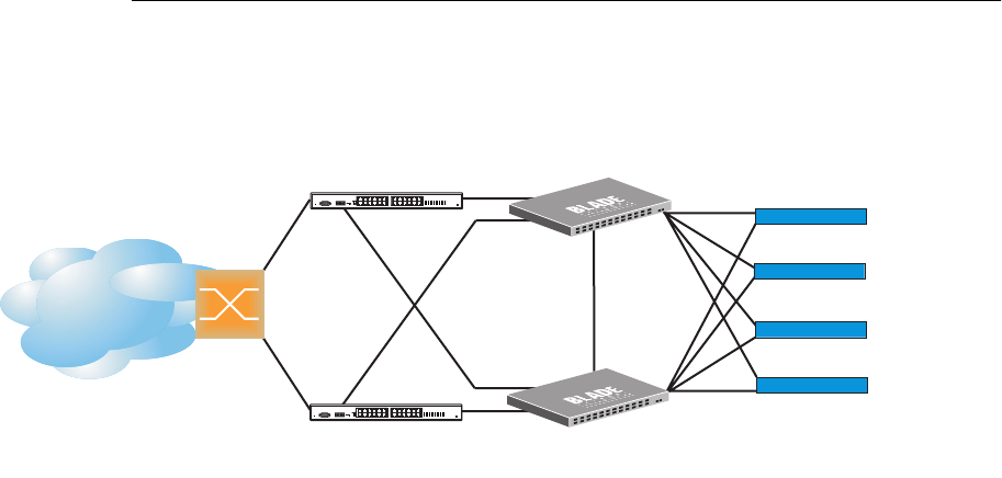
Figure 43 shows an example configuration where two G8124s are used as VRRP routers in an
active-active configuration. In this configuration, both switches respond to packets.
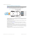
Figure 43 Active-Active High-Availability Configuration
Although this example shows only two switches, there is no limit on the number of switches used in
a redundant configuration. It is possible to implement an active-active configuration across all the
VRRP-capable switches in a LAN.
Each VRRP-capable switch in an active-active configuration is autonomous. Switches in a virtual
router need not be identically configured.
In the scenario illustrated in Figure 43, traffic destined for IPv4 address 10.0.1.1 is forwarded
through the Layer 2 switch at the top of the drawing, and ingresses G8124 1 on port 1. Return traffic
uses default gateway 1 (192.168.1.1).
If the link between G8124 1 and the Layer 2 switch fails, G8124 2 becomes the Master because it
has a higher priority. Traffic is forwarded to G8124 2, which forwards it to G8124 1 through port 4.
Return traffic uses default gateway 2 (192.168.2.1), and is forwarded through the Layer 2 switch at
the bottom of the drawing.
To implement the active-active example, perform the following switch configuration.
Internet
Internet
Enterprise
Routing Switch
Switch 1
Switch 2
VIR 1: 192.168.1.200 (Master)
VIR 2: 192.168.2.200 (Backup)
VIR 1: 192.168.1.200 (Backup)
VIR 2: 192.168.2.200 (Master)
NIC 1: 10.0.1.1/24
NIC 2: 10.0.2.1/24
NIC 1: 10.0.1.2/24
NIC 2: 10.0.2.2/24
NIC 1: 10.0.1.3/24
NIC 2: 10.0.2.3/24
NIC 1: 10.0.1.4/24
NIC 2: 10.0.2.4/24
L2 Switch
L2 Switch
1
2
4
1
2
Server 1
Server 2
Server 3
Server 4