


BLADEOS 6.5.2 Application Guide
228 Chapter 15: Basic IP Routing BMD00220, October 2010
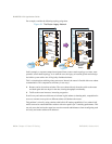
When a switch receives a UDP broadcast on port 67 from a DHCP client requesting an IP address,
the switch acts as a proxy for the client, replacing the client source IP (SIP) and destination IP (DIP)
addresses. The request is then forwarded as a UDP Unicast MAC layer message to two BOOTP
servers whose IP addresses are configured on the switch. The servers respond as a UDP Unicast
message back to the switch, with the default gateway and IP address for the client. The destination
IP address in the server response represents the interface address on the switch that received the
client request. This interface address tells the switch on which VLAN to send the server response to
the client.
To enable the G8124 to be the BOOTP forwarder, you need to configure the DHCP/BOOTP server
IP addresses on the switch. Generally, you should configure the switch IP interface on the client side
to match the client’s subnet, and configure VLANs to separate client and server subnets. The DHCP
server knows from which IP subnet the newly allocated IP address should come.
In G8124 implementation, there is no need for primary or secondary servers. The client request is
forwarded to the BOOTP servers configured on the switch. The use of two servers provide failover
redundancy. However, no health checking is supported.
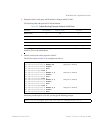
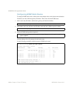
Use the following commands to configure the switch as a DHCP relay agent:
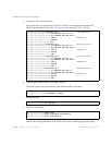
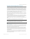
Additionally, DHCP Relay functionality can be assigned on a per interface basis. Use the following
commands to enable the Relay functionality:
RS G8124(config)# ip bootp-relay server 1 <IP address>
RS G8124(config)# ip bootp-relay server 2 <IP address>
RS G8124(config)# ip bootp-relay enable
RS G8124(config)# show ip bootp-relay
RS G8124(config)# interface ip <Interface number>
RS G8124(config-ip-if)# relay