


BLADEOS 6.5.2 Application Guide
268 Chapter 19: Border Gateway Protocol BMD00220, October 2010
BGP Failover Configuration
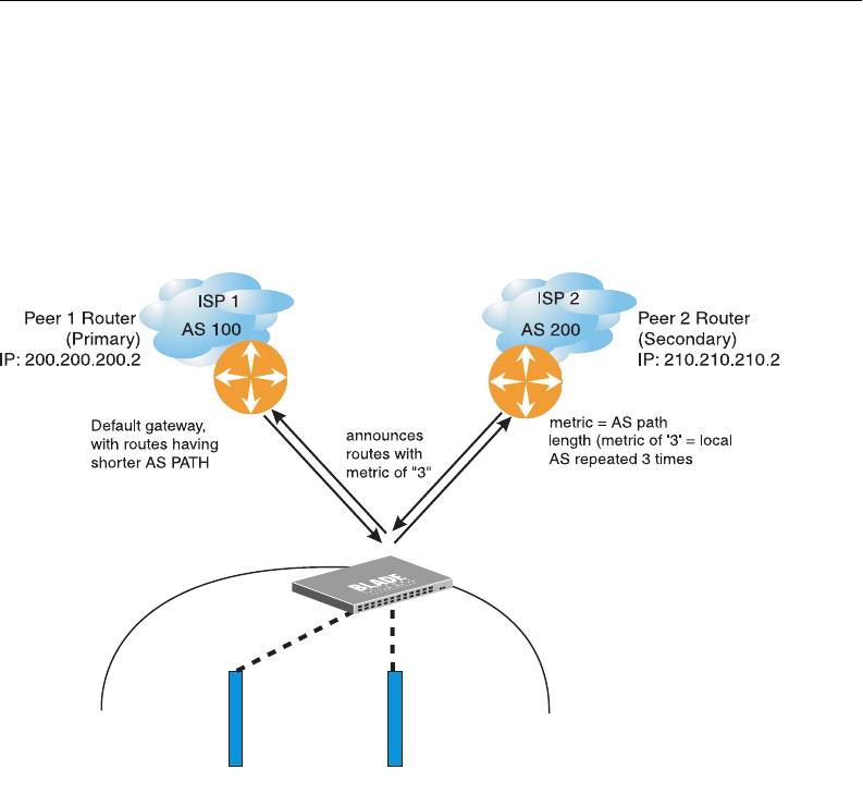
Use the following example to create redundant default gateways for a G8124 at a Web Host/ISP
site, eliminating the possibility, should one gateway go down, that requests will be forwarded to an
upstream router unknown to the switch.
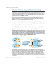
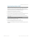
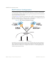
As shown in Figure 28, the switch is connected to ISP 1 and ISP 2. The customer negotiates with
both ISPs to allow the switch to use their peer routers as default gateways. The ISP peer routers will
then need to announce themselves as default gateways to the G8124.
Figure 28 BGP Failover Configuration Example
On the G8124, one peer router (the secondary one) is configured with a longer AS path than the
other, so that the peer with the shorter AS path will be seen by the switch as the primary default
gateway. ISP 2, the secondary peer, is configured with a metric of “3,” thereby appearing to the
switch to be three router hops away.
BladeCenter
BLADE switch
Server 1
IP: 200.200.200.10
Server 2
IP: 200.200.200.11
IP: 200.200.200.1
IP: 210.210.210.1