


BLADEOS 6.5.2 Application Guide
BMD00220, October 2010 Chapter 6: VLANs 91
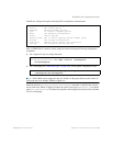
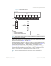
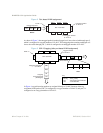
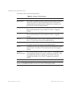
Figure 1 Default VLAN settings
Note – The port numbers specified in these illustrations may not directly correspond to the physical
port configuration of your switch model.
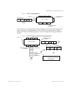
When a VLAN is configured, ports are added as members of the VLAN, and the ports are defined as
either tagged or untagged (see Figure 2 through Figure 5).
The default configuration settings for the G8124 has all ports set as untagged members of VLAN 1
with all ports configured as PVID = 1. In the default configuration example shown in Figure 1, all
incoming packets are assigned to VLAN 1 by the default port VLAN identifier (PVID =1).
Figure 2 through Figure 5 illustrate generic examples of VLAN tagging. In Figure 2, untagged
incoming packets are assigned directly to VLAN 2 (PVID = 2). Port 5 is configured as a tagged
member of VLAN 2, and port 7 is configured as an untagged member of VLAN 2.
Note – The port assignments in the following figures are not meant to match the G8124.
Port 1
DA
SA
Data
CRC
Incoming
untagged
packet
BS45010A
Port 2 Port 3 Port 4 Port 5
VLAN 1
802.1Q Switch
By default:
Key
All ports are assigned PVID = 1
All ports are untagged members of VLAN 1
PVID = 1
Port 6 ...
DA
SA
Data
CRC
Outgoing
untagged packet
(unchanged)
Port 7