


BLADEOS 6.5.2 Application Guide
292 Chapter 20: OSPF BMD00220, October 2010
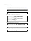
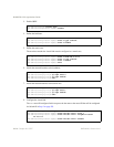
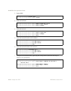
3. Enable OSPF.
4. Define the backbone.
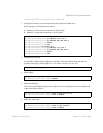
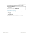
5. Define the transit area.
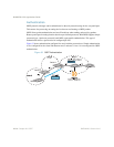
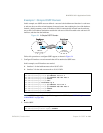
The area that contains the virtual link must be configured as a transit area.
6. Attach the network interface to the backbone.
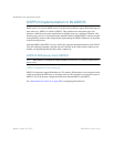
7. Attach the network interface to the transit area.
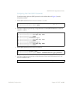
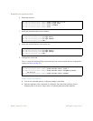
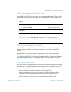
8. Configure the virtual link.
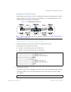
The nbr router ID configured in this step must be the same as the router ID that will be configured
for Switch #2 in Step 2 on page 293.
RS G8124(config)# router ospf
RS G8124(config-router-ospf)# enable
RS G8124(config-router-ospf)# area 0 area-id 0.0.0.0
RS G8124(config-router-ospf)# area 0 type transit
RS G8124(config-router-ospf)# area 0 enable
RS G8124(config-router-ospf)# area 1 area-id 0.0.0.1
RS G8124(config-router-ospf)# area 1 type transit
RS G8124(config-router-ospf)# area 1 enable
RS G8124(config-router-ospf)# exit
RS G8124(config)# interface ip 1
RS G8124(config-ip-if)# ip ospf area 0
RS G8124(config-ip-if)# ip ospf enable
RS G8124(config-ip-if)# exit
RS G8124(config)# interface ip 2
RS G8124(config-ip-if)# ip ospf area 1
RS G8124(config-ip-if)# ip ospf enable
RS G8124(config-ip-if)# exit
RS G8124(config)# router ospf
RS G8124(config-router-ospf)# area-virtual-link 1 area 1
RS G8124(config-router-ospf)# area-virtual-link 1 neighbor-router
10.10.14.1
RS G8124(config-router-ospf)# area-virtual-link 1 enable