


BLADEOS 6.5.2 Application Guide
BMD00220, October 2010 Chapter 19: Border Gateway Protocol 269
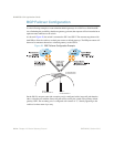
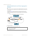
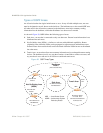
1. Define the VLANs.
For simplicity, both default gateways are configured in the same VLAN in this example. The
gateways could be in the same VLAN or different VLANs
.
2. Define the IP interfaces with IPv4 addresses.
The switch will need an IP interface for each default gateway to which it will be connected. Each
interface must be placed in the appropriate VLAN. These interfaces will be used as the primary and
secondary default gateways for the switch.
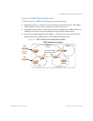
3. Enable IP forwarding.
IP forwarding is turned on by default and is used for VLAN-to-VLAN (non-BGP) routing. Make
sure IP forwarding is on if the default gateways are on different subnets or if the switch is connected
to different subnets and those subnets need to communicate through the switch (which they almost
always do).
Note – To help eliminate the possibility for a Denial of Service (DoS) attack, the forwarding of
directed broadcasts is disabled by default.
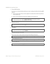
4. Configure BGP peer router 1 and 2 with IPv4 addresses.
>> # vlan 1
>> (config-vlan)# member <port number>
>> # interface ip 1
>> (config-ip-if)# ip address 200.200.200.1
>> (config-ip-if)# ip netmask 255.255.255.0
>> (config-ip-if)# enable
>> (config-ip-if)# exit
>> # interface ip 2
>> (config-ip-if)# ip address 210.210.210.1
>> (config-ip-if)# ip netmask 255.255.255.0
>> (config-ip-if)# enable
>> (config-ip-if)# exit
>> # ip routing
>> # router bgp
>> (config-router-bgp)# neighbor 1 remote-address 200.200.200.2
>> (config-router-bgp)# neighbor 1 remote-as 100
>> (config-router-bgp)# neighbor 2 remote-address 210.210.210.2
>> (config-router-bgp)# neighbor 2 remote-as 200