


BLADEOS 6.5.2 Application Guide
122 Chapter 8: Spanning Tree Protocols BMD00220, October 2010
Configuring Multiple STGs
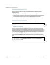
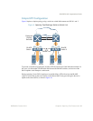
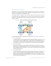
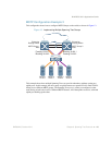
This configuration shows how to configure the three instances of STGs on the switches A, B, C, and
D illustrated in Figure 12 on page 121.
By default Spanning Trees 2 to 127 are empty, and STG 1 contains all configured VLANs until
individual VLANs are explicitly assigned to other STGs.
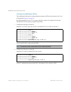
1. Configure the following on Switch A:
Add port 17 to VLAN 2, port 18 to VLAN 3, and define STG 2 for VLAN 2 and VLAN 3.
VLAN 2 and VLAN 3 are removed from STG 1.
Note – In STP/PVST+ mode, each instance of STG is enabled by default.
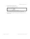
2. Configure the following on Switch B:
Add port 8 to VLAN 2 and define STG 2 for VLAN 2.
VLAN 2 is automatically removed from STG 1. By default VLAN 1 remains in STG 1.
RS G8124(config)# vlan 2
RS G8124(config-vlan)# enable
RS G8124(config-vlan)# member 17
RS G8124(config-vlan)# exit
RS G8124(config)# vlan 3
RS G8124(config-vlan)# enable
RS G8124(config-vlan)# member 18
RS G8124(config-vlan)# exit
RS G8124(config)# spanning-tree stp 2 vlan 2,3
RS G8124(config)# vlan 2
RS G8124(config-vlan)# enable
RS G8124(config-vlan)# member 8
RS G8124(config-vlan)# exit
RS G8124(config)# spanning-tree stp 2 vlan 2