


BLADEOS 6.5.2 Application Guide
326 Chapter 23: Layer 2 Failover BMD00220, October 2010
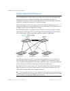
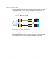
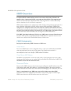
Figure 41 is a simple example of Layer 2 Failover. One G8124 is the primary, and the other is used
as a backup. In this example, all ports on the primary switch belong to a single trunk group, with
Layer 2 Failover enabled, and Failover Limit set to 2. If two or fewer links in trigger 1 remain
active, the switch temporarily disables all control ports. This action causes a failover event on
Server 1 and Server 2.
Figure 41 Basic Layer 2 Failover
Setting the Failover Limit
The failover limit lets you specify the minimum number of operational links required within each
trigger before the trigger initiates a failover event. For example, if the limit is two, a failover event
occurs when the number of operational links in the trigger is two or fewer. When you set the limit to
zero, the switch triggers a failover event only when no links in the trigger are operational.
Trigger 1
Trigger 1
Primary
Switch
Backup
Switch
Server 1
Server 2
NIC 1
NIC 2
NIC 1
NIC 2
Internet
Enterprise
Routing Switches