


BLADEOS 6.5.2 Application Guide
BMD00220, October 2010 Chapter 15: Basic IP Routing 223
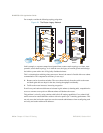
3. Determine which switch ports and IP interfaces belong to which VLANs.
The following table adds port and VLAN information:
Note – To perform this configuration, you must be connected to the switch Command Line
Interface (CLI) as the administrator.
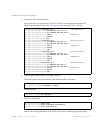
4. Add the switch ports to their respective VLANs.
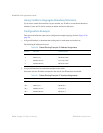
The VLANs shown in Table 22 are configured as follows:
Each time you add a port to a VLAN, you may get the following prompt:
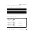
Table 22 Subnet Routing Example: Optional VLAN Ports
Devices IP Interface Switch Ports VLAN #
Default router 1 22 1
Web servers 2 1 and 2 2
Database servers 3 3 and 4 3
Terminal Servers 4 5 and 6 4
RS G8124(config)# vlan 1
RS G8124(config-vlan)# member 22 (Add ports to VLAN 1)
RS G8124(config-vlan)# enable
RS G8124(config-vlan)# exit
RS G8124(config)# vlan 2
RS G8124(config-vlan)# member 1,2 (Add ports to VLAN 2)
RS G8124(config-vlan)# enable
RS G8124(config-vlan)# exit
RS G8124(config)# vlan 3
RS G8124(config-vlan)# member 3,4 (Add ports to VLAN 3)
RS G8124(config-vlan)# enable
RS G8124(config-vlan)# exit
RS G8124(config)# vlan 4
RS G8124(config-vlan)# member 5,6 (Add ports to VLAN 4)
RS G8124(config-vlan)# enable
RS G8124(config-vlan)# exit
Port 4 is an untagged port and its PVID is changed from 1 to 3.