


BLADEOS 6.5.2 Application Guide
202 Chapter 14: FCoE and CEE BMD00220, October 2010
PFC Configuration Example
Note – DCBX may be configured to permit sharing or learning PFC configuration with or from
external devices. This example assumes that PFC configuration is being performed manually. See
“Data Center Bridging Capability Exchange” on page 211 for more information on DCBX.
This example is consistent with the network shown in Figure 22 on page 189. In this example, the
following topology is used.
In this example, PFC is to facilitate lossless traffic handling for FCoE (priority value 3) and a
business-critical LAN application (priority value 4).
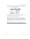
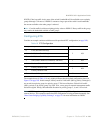
Assuming that CEE is off (the G8124 default), the example topology shown in Table 18 can be
configured using the following commands:
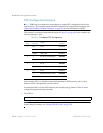
1. Turn CEE on.
Note – Turning CEE on will automatically change some 802.1p QoS and 802.3x standard flow
control settings and menus (see “Turning CEE On or Off” on page 192).
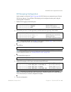
Table 18 Port-Based PFC Configuration
Switch
Port
802.1p
Priority
Usage
PFC
Setting
1 0-2 LAN Disabled
4 Business-critical LAN Enabled
others (not used) Disabled
2 3 FCoE (to FCF bridge) Enabled
others (not used) Disabled
33 FCoE Enabled
others (not used) Disabled
4 0-2 LAN Disabled
4 Business-critical LAN Enabled
others (not used) Disabled
RS G8124(config)# cee enable