


1-75
Cisco ONS 15327 Troubleshooting Guide, R3.4
April 2003
Chapter 1 General Troubleshooting
Fiber and Cabling
Table 1-37 shows the pinout of a LAN cable.
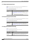
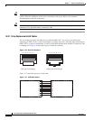
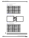
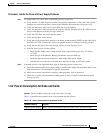
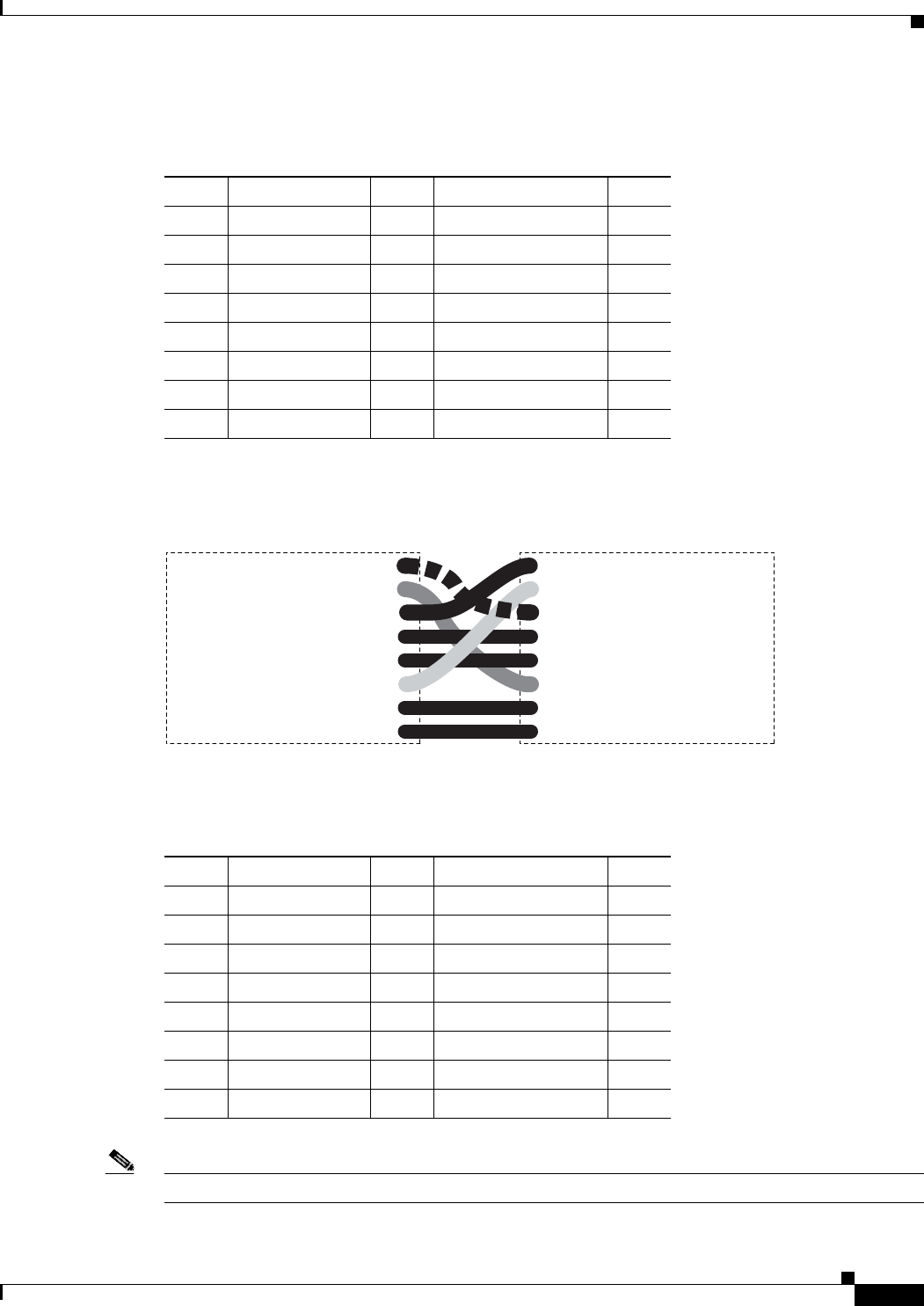
Figure 1-28 on page 1-75 shows the layout of a cross-over cable.
Figure 1-28 Cross-Over Cable Layout
Table 1-38 shows the pinout of a cross-over cable.
Note Odd-numbered pins always connect to a white wire with a colored stripe.
Table 1-37 LAN Cable Pinout
Pin Color Pair Name Pin
1 White/orange 2 Transmit Data + 1
2 Orange 2 Transmit Data - 2
3 White/green 3 Receive Data + 3
4Blue 1 4
5 White/blue 1 5
6 Green 3 Receive Data - 6
7 White/brown 4 7
8Brown 4 8
1
2
3
4
5
6
7
8
1
2
3
4
5
6
7
8
55416
Table 1-38 Cross-Over Cable Pinout
Pin Color Pair Name Pin
1 White/orange 2 Transmit Data + 3
2 Orange 2 Transmit Data – 6
3 White/green 3 Receive Data + 1
4Blue 1 4
5 White/blue 1 5
6 Green 3 Receive Data – 2
7 White/brown 4 7
8Brown 4 8