


3-3
Cisco ONS 15327 Troubleshooting Guide, R3.4
April 2003
Chapter 3 Replace Hardware
Remove and Reinsert (Reseat) the Standby XTC
Note The FAN STATUS LED only illuminates when an XTC card is installed.
3.2 Remove and Reinsert (Reseat) the Standby XTC
Caution Do not perform this action without the supervision and direction of the Cisco Technical Assistance
Center (TAC). The Cisco TAC can be reached at (1-800-553-2447).
Note To determine whether you have an active or standby XTC, position the cursor over the XTC card graphic
to display the status.
Step 1 Ensure that the XTC you want to reset is in standby mode. On the XTC card, the ACT/STBY
(Active/Standby) LED is amber when the XTC is in standby mode.
Step 2 When the XTC is in standby mode, unlatch both the top and bottom ejector levers on the XTC card.
Step 3 Physically pull the card at least partly out of the slot until the lighted LEDs turn off.
Step 4 Wait 30 seconds. Reinsert the card and close the ejector levers.
Note The XTC will take several minutes to reboot and will display the amber standby LED after
rebooting. Refer to the Cisco ONS 15327 Procedure Guide for more information about LED
behavior during XTC reboots.
3.3 Inspect, Clean, and Replace the Reusable Air Filter
Warning
Do not reach into a vacant slot or chassis while you install or remove a module or a fan. Exposed
circuitry could constitute an energy hazard.
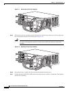
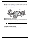
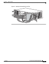
Note The Cisco ONS 15327 air filter should be removed and visually inspected approximately every 30 days,
depending on the cleanliness of the operating environment. The filter is reusable and made of a gray
open-cell polyurethane foam, specially coated to provide fire and fungi resistance. Figure 3-3 on
page 3-4 illustrates the reusable fan-tray air filter. You do not need to remove the fan-tray assembly to
remove the air filter.