


1-39
Cisco ONS 15327 Troubleshooting Guide, R3.4
April 2003
Chapter 1 General Troubleshooting
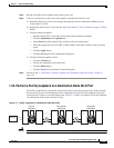
Identify Points of Failure on an OC-N Circuit Path
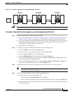
Procedure: Create the Terminal Loopback on a Destination Node OC-N Port
Step 1 Connect an optical test set to the port you are testing:
a. If you just completed the “Perform a Facility Loopback on a Destination-Node OC-N Port”
procedure on page 1-35, leave the optical test set hooked up to the OC-N port in the source node.
b. If you are starting the current procedure without the optical test set hooked up to the OC-N port, use
appropriate cabling to attach the Tx and Rx terminals of the optical test set to the port you are
testing. Both Tx and Rx connect to the same port.
c. Adjust the test set accordingly.
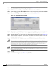
Step 2 Use CTC to set up the terminal loopback circuit on the port being tested:
a. Click the Circuits tab and click the Create button.
b. Give the circuit an easily identifiable name, such as OCN1toOCN6.
c. Set circuit Type and Size to the normal preferences.
d. Leave the Bidirectional check box checked and click the Next button.
e. In the Circuit Source dialog box, fill in the source Node, card Slot, Port, and Type where the test
set is connected and click the Next button.
f. In the Circuit Destination dialog box, fill in the destination Node, card Slot, Port, and Type (the
OC-N port in the destination node) and click the Finish button.
Step 3 Confirm that the newly created circuit appears on the Circuits tab list as a two-way circuit.
Note It is normal for a LPBKTERMINAL condition to appear during a loopback setup. The condition
clears when you remove the loopback.
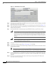
Step 4 Create the terminal loopback on the destination port being tested:
a. Go to the node view of the destination node:
• Choose View > Go To Other Node from the menu bar.
• Choose the node from the drop-down list in the Select Node dialog box and click the OK button.
b. In node view, double-click the card that requires the loopback, such as the destination OC-N card in
the destination node.
c. Click the Maintenance > Loopback tabs.
d. Select OOS_MT from the State column. If this is a multiport card, select the row appropriate for
the desired port.
e. Select Terminal (Inward) from the Loopback Type column. If this is a multiport card, select the
row appropriate for the desired port.
f. Click the Apply button.
g. Click the Yes button in the Confirmation Dialog box.
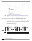
Step 5 Proceed to the “Test the Terminal Loopback Circuit” procedure on page 1-40.