


3-2
Cisco ONS 15327 Troubleshooting Guide, R3.4
April 2003
Chapter 3 Replace Hardware
Replace the Fan-Tray Assembly
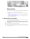
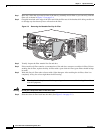
Figure 3-1 Removing the Fan-Tray Assembly
Step 5 Slide the new fan-tray assembly into the shelf until the electrical plug at the rear of the tray plugs into
the corresponding receptacle on the back panel (Figure 3-2).
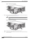
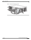
Caution Do not force the fan-tray assembly into place while installing it. Forcing the fan-tray assembly
into place can damage the connectors on the fan tray and/or the connectors on the shelf
assembly.
Figure 3-2 Replacing the Fan-Tray Assembly
Step 6 Secure the fan-tray assembly into the slot using the attached fastening screw.
Step 7 Confirm that the FAN STATUS LED on the front of the fan-tray assembly is illuminated. This indicates
that the fan is operating.
1
2
3
4
E10/100-T
F
A
IL
A
C
T
S
F
1
2
3
4
E10/100-T
F
A
IL
A
C
T
S
F
OC12/STM-4
IR 1310
F
A
IL
A
C
T
S
F
OC48/STM-16
IR 1310
F
A
IL
A
C
T
S
F
ACO
LAN
CRAFT
XTC-28-3
LAMP
TEST
FAI L
ACT/STBY
SYNC
ACO
DS3 SF
DS1 SF
PWR A
PWR B
CRIT
MAJ
MIN
REM
ACO
LAN
CRAFT
XTC-28-3
LAMP
TEST
FAI L
ACT/STBY
SYNC
ACO
DS3 SF
DS1 SF
PWR A
PWR B
CRIT
MAJ
MIN
REM
BITS
MIC B
ALARM
DS1 (15-28)
-48VRET
PWR B
Rx 1
Rx 2
Rx 3
BITS
MIC A
ALARM
DS1 (15-28)
-48V
RET
PWR B
Tx 1
Tx 2
Tx 3
CISCO O
NS 15327
OPTICAL NETW
ORKING SYSTEM
FAN
STATUS
71537
CISCO O
NS 15327
OPTICAL NETW
ORKING SYSTEM
FAN
STATUS
1
2
3
4
E10/100-T
F
A
IL
A
C
T
S
F
1
2
3
4
E10/100-T
F
A
IL
A
C
T
S
F
OC12/STM-4
IR 1310
F
A
IL
A
C
T
S
F
OC48/STM-16
IR 1310
F
A
IL
A
C
T
S
F
ACO
LAN
CRAFT
XTC-28-3
LAMP
TEST
FAI L
ACT/STBY
SYNC
ACO
DS3 SF
DS1 SF
PWR A
PWR B
CRIT
MAJ
MIN
REM
ACO
LAN
CRAFT
XTC-28-3
LAMP
TEST
FAI L
ACT/STBY
SYNC
ACO
DS3 SF
DS1 SF
PWR A
PWR B
CRIT
MAJ
MIN
REM
BITS
MIC B
ALARM
DS1 (15-28)
-48VRET
PWR B
Rx 1
Rx 2
Rx 3
BITS
MIC A
ALARM
DS1 (15-28)
-48V
RET
PWR B
Tx 1
Tx 2
Tx 3
CISCO ONS 15327
OPTICAL NETWORKING SYSTEM
FAN
STATUS
71535
CISCO ONS 15327
OPTICAL NETWORKING SYSTEM
FAN
STATUS