


1-15
Cisco ONS 15327 Troubleshooting Guide, R3.4
April 2003
Chapter 1 General Troubleshooting
Identify Points of Failure on a DS-N Circuit Path
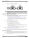
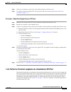
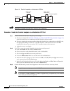
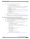
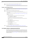
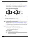
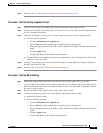
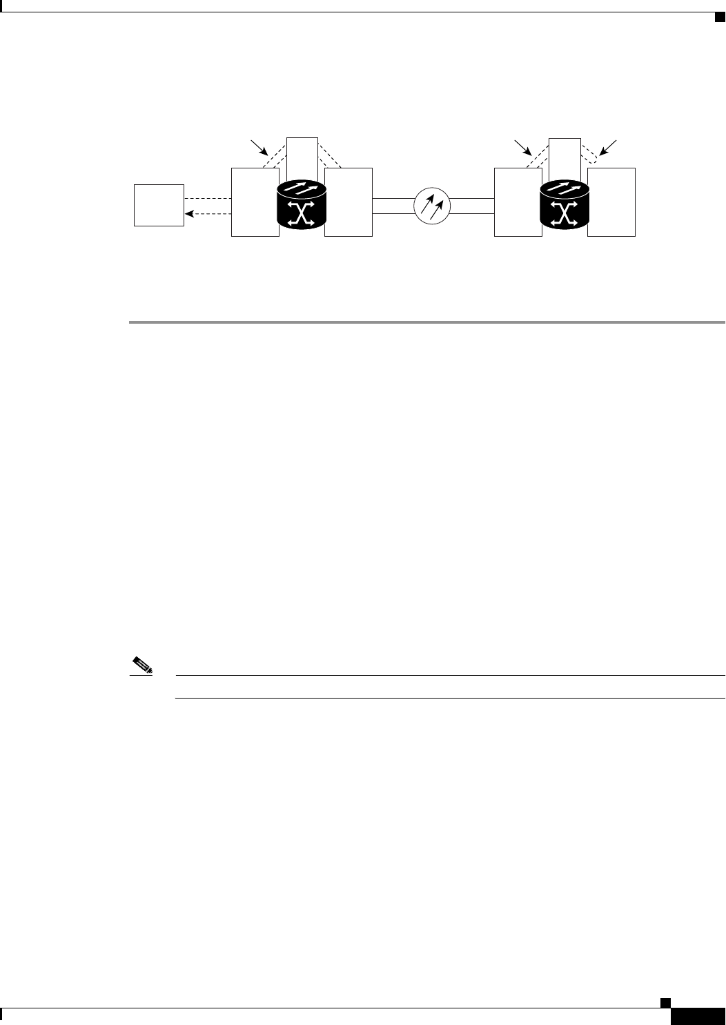
Figure 1-10 Hairpin on a Destination Node XTC Card
Procedure: Create the Hairpin Loopback Circuit on the Destination Node XTC Card
Step 1 Connect an electrical test set to the port you are testing.
Use appropriate cabling to attach the Tx and Rx terminals of the electrical test set to the EIA connectors
or DSx panel for the port you are testing. The Tx and Rx terminals connect to the same port. Adjust the
test set accordingly.
Step 2 Use CTC to set up the source loopback circuit on the port being tested:
a. Click the Circuits tab and click the Create button.
b. Give the circuit an easily identifiable name, such as Hairpin1.
c. Set the circuit Type and Size to the normal preferences.
d. Leave the Bidirectional check box checked and click the Next button.
e. In the Circuit Source dialog box, fill in the source Node, card Slot, Port, and Type where the test
set is connected and click the Next button.
f. In the Circuit Destination dialog box, fill in the destination Node, card Slot, Port, and Type (the
port in the destination node) and click the Finish button.
Step 3 Confirm that the newly created circuit appears on the Circuits tab list as a two-way circuit.
Step 4 Use CTC to set up the destination hairpin circuit on the port being tested.
Note The destination loopback circuit on a port is a one-way test.
For example, in a typical east-to-west slot configuration, a Slot 1 (east) OC-N card on the source node
is one end of the fiber span, and the Slot 2 (west) OC-N card on the destination node is the other end.
a. Click the Circuits tab and click the Create button.
b. Give the circuit an easily identifiable name, such as Hairpin1.
c. Set the Circuit Type and Size to the normal preferences.
d. Uncheck the Bidirectional check box and click the Next button.
e. In the Circuit Source dialog box, select the same Node, card Slot, Port, and Type where the previous
circuit is connected and click the Next button.
f. In the Circuit Destination dialog box, use the same Node, card Slot, Port, and Type used for the
Circuit Source dialog box and click the Finish button.
Step 5 Confirm that the newly created circuit appears on the Circuits tab list as a one-way circuit.
Hairpin
Bidirectional
circuit
Unidirectional
circuit
MIC OC-N OC-N MIC
DS-N
DS-N
Slot 1
Slot 2
Slot 2
Slot 1
Test Set A
OC-N
XTC
XTC
ONS 15327
Source
ONS 15327
Destination
76189