


1-26
Cisco ONS 15327 Troubleshooting Guide, R3.4
April 2003
Chapter 1 General Troubleshooting
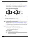
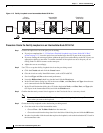
Identify Points of Failure on an OC-N Circuit Path
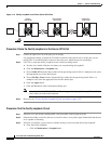
Procedure: Retest the Original XTC Card
Step 1 Do a manual switch of the XTC cards to make the original XTC card the active card:
a. Determine the active cross-connect card. On both the physical node and the CTC window, the active
XTC has a green ACT LED, and the standby XTC has an amber SBY LED.
b. Position the cursor over the active cross-connect card.
c. Right-click and choose Reset from the shortcut menu.
d. On the Resetting Card dialog box, click Yes. After 20 to 40 seconds, a “lost node connection,
changing to network view” message is displayed.
e. Click OK. On the network view map, the node where you reset the XTC is gray.
f. After the node icon turns green (within 1 to 2 minutes), double-click it. On the shelf graphic, observe
the following:
• The previous standby XTC displays a green ACT LED.
• The previous active XTC LEDs go through the following LED sequence: NP (card not present),
Ldg (software is loading), amber SBY LED (XTC is in standby mode).
• The LEDs should complete this sequence within 5 to 10 minutes.
Step 2 Resend test traffic on the loopback circuit.
Step 3 If the test set indicates a faulty circuit, the problem is probably the defective card:
a. Return the defective card to Cisco through the returned materials authorization (RMA) process.
Contact the Cisco TAC.
b. Replace the faulty XTC card. See “Physically Replace a Card” procedure on page 2-130 for details.
c. Clear the cross-connect loopback:
• Click the Circuits tab.
• Choose the cross-connect loopback circuit being tested.
• Click the Delete button.
• Click the Yes button in the Delete Circuits dialog box.
d. Proceed to Step 5.
Step 4 If the test set indicates a good circuit, the XTC card might have had a temporary problem that is cleared
by the switch.
Clear the cross-connect loopback:
a. Click the Circuits tab.
b. Choose the cross-connect loopback circuit being tested.
c. Click the Delete button.
d. Click the Yes button in the Delete Circuits dialog box.
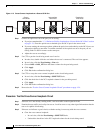
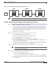
Step 5 Proceed to the “1.3.3 Perform a Terminal Loopback on a Source-Node OC-N Port” section on page 1-27.