


1-67
Cisco ONS 15327 Troubleshooting Guide, R3.4
April 2003
Chapter 1 General Troubleshooting
Circuits and Timing
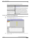
Procedure: View the State of Circuit Nodes
Step 1 Click the Circuits tab.
Step 2 From the Circuits tab list, select the circuit with the *_PARTIAL state condition.
Step 3 Click the Edit button. The Edit Circuit window appears.
Step 4 In the Edit Circuit window, click the State tab.
The State tab window lists the Node, CRS End A, CRS End B, and CRS State for each of the nodes in
the circuit.
1.7.2 AIS-V on XTC-28-3 Unused VT Circuits
Symptom An incomplete circuit path causes an alarm indications signal (AIS).
Table 1-26 describes the potential cause of the symptom and the solution.
Procedure: Clear AIS-V on XTC-28-3 Unused VT Circuits
Step 1 Determine the affected port.
Step 2 Record the node ID, slot number, port number, and VT number.
Step 3 Create a unidirectional VT circuit from the affected port back to itself, such as
Source node/Slot 2/Port 2/VT 13 cross connected to Source node/Slot 2/Port 2/VT 13.
During an automatic
transition, some
path-level defects
and/or alarms were
detected on the circuit.
Determine which node in the circuit is not changing to the desired state.
Refer to the “View the State of Circuit Nodes” procedure on page 1-67.
Log into the circuit node that did not change to the desired state and examine
the circuit for path-level defects, improper circuit termination, or alarms.
Refer to the Cisco ONS 15327 Procedure Guide for procedures to clear
alarms and change circuit configuration settings.
Resolve and clear the defects and/or alarms on the circuit node and verify
that the circuit transitions to the desired state.
One end of the circuit is
not properly terminated.
Table 1-25 Circuit in Partial State (continued)
Possible Problem Solution
Table 1-26 AIS-V on XTC-28-3 Unused VT Circuits
Possible Problem Solution
The port on the
reporting node is
in-service but a node
upstream on the circuit
does not have an OC-N
port in service.
An AIS-V indicates that an upstream failure occurred at the virtual tributary
(VT) layer. AIS-V alarms also occur on XTC-28-3 VT circuits that are not
carrying traffic and on stranded bandwidth.
Perform the “Clear AIS-V on XTC-28-3 Unused VT Circuits” procedure on
page 1-67.