Important Points to Remember
• Before using the QSA to convert a 40 Gigabit Ethernet port to a 10 Gigabit SFP or SFP+ port, enable
40 G to 4*10 fan-out mode on the device.
• When you insert a QSA into a 40 Gigabit port, you can use only the first 10 Gigabit port in the fan-out
mode to plug-in SFP or SFP+ cables. The remaining three 10 Gigabit ports are perceived to be in Link
Down state and are unusable.
• You cannot use QSFP Optical cables on the same port where QSA is used.
• When you remove the QSA module alone from a 40 Gigabit port, without connecting any SFP or SFP
+ cables; Dell Networking OS does not generate any event. However, when you remove a QSA
module that has SFP or SFP+ optical cables plugged in, Dell Networking OS generates an SFP or SFP+
Removed event.
• The QSA module does not have a designated EEPROM. To recognize a QSA, Dell Networking OS
reads the EEPROM corresponding to an SFP+ or SFP module that is plugged into QSA. The access
location of this EEPROM is different from the EEPROM location of the QSFP+ module.
• The diagnostics application is capable of detecting insertion or removal of both the QSA as well as the
SFP+ or SFP optical cables plugged into the QSA. In addition, the diagnostic application is also
capable of reading the DDS and Vendor information from the EEPROM corresponding to SFP+ or SFP
optical cables. As a result, no separate detection of QSA is required.
Example Scenarios
Consider the following scenarios:
• QSFP port 0 is connected to a QSA with SFP+ optical cables plugged in.
• QSFP port 4 is connected to a QSA with SFP optical cables plugged in.
• QSFP port 8 in fanned-out mode is plugged in with QSFP optical cables.
• QSFP port 12 in 40 G mode is plugged in with QSFP optical cables.
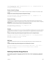
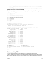
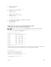
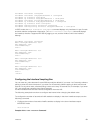
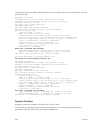
For these configurations, the following examples show the command output that the show interfaces
tengigbitethernet transceiver, show interfaces tengigbitethernet, and show
inventory media
commands displays:
NOTE: In the following show interfaces tengigbitethernet commands, the ports 1,2, and 3
are inactive and no physical SFP or SFP+ connection actually exists on these ports. However, Dell
Networking OS still perceives these ports as valid and the output shows that pluggable media
(optical cables) is inserted into these ports. This is a software limitation for this release.
Layer 2 Flow Control Using Ethernet Pause Frames
Ethernet pause frames allow for a temporary stop in data transmission.
A situation may arise where a sending device may transmit data faster than a destination device can
accept it. The destination sends a pause frame back to the source, stopping the sender’s transmission for
a period of time.
Interfaces
425


