


Important Points to Remember
• VLT port channel interfaces must be switch ports.
• If you include RSTP on the system, configure it before VLT. Refer to RSTP Configuration.
• Ensure that the spanning tree root bridge is at the Aggregation layer. If you enable RSTP on the VLT
device, refer to RSTP and VLT for guidelines to avoid traffic loss.
• If you reboot both VLT peers in BMP mode and the VLT LAGs are static, the DHCP server reply to the
DHCP discover offer may not be forwarded by the ToR to the correct node. To avoid this scenario,
configure the VLT LAGs to the ToR and the ToR port channel to the VLT peers with LACP. If supported
by the ToR, enable the lacp-ungroup feature on the ToR using the lacp ungroup member-
independent port-channel command.
• If the lacp-ungroup feature is not supported on the ToR, reboot the VLT peers one at a time. After
rebooting, verify that VLTi (ICL) is active before attempting DHCP connectivity.
• When you enable IGMP snooping on the VLT peers, ensure the value of the delay-restore
command is not less than the query interval.
• When you enable Layer 3 routing protocols on VLT peers, make sure the delay-restore timer is set to a
value that allows sufficient time for all routes to establish adjacency and exchange all the L3 routes
between the VLT peers before you enable the VLT ports.
• Only use the lacp ungroup member-independent command if the system connects to nodes
using bare metal provisioning (BMP) to upgrade or boot from the network.
• Ensure that you configure all port channels where LACP ungroup is applicable as hybrid ports and as
untagged members of a VLAN. BMP uses untagged dynamic host configuration protocol (DHCP)
packets to communicate with the DHCP server.
• If the DHCP server is located on the ToR and the VLTi (ICL) is down due to a failed link when a VLT
node is rebooted in BMP mode, it is not able to reach the DHCP server, resulting in BMP failure.
• If the source is connected to an orphan (non-spanned, non-VLT) port in a VLT peer, the receiver is
connected to a VLT (spanned) port-channel, and the VLT port-channel link between the VLT peer
connected to the source and TOR is down, traffic is duplicated due to route inconsistency between
peers. To avoid this scenario, Dell Networking recommends configuring both the source and the
receiver on a spanned VLT VLAN.
• In a topology in which two VLT peer nodes that are connected by a VLTi link and are connected to a
ToR switch using a VLT LAG interface, if you configure an egress IP ACL and apply it on the VLT LAG
of both peers using the deny ip any any command, the traffic is permitted on the VLT LAG instead
of being denied. The correct behavior of dropping the traffic on the VLT LAG occurs when VLT is up
on both the peer nodes. However, if VLT goes down on one of the peers, traffic traverses through
VLTi and the other peer switches it to the VLT LAG. Although egress ACL is applied on the VLT nodes
to deny all traffic, this egress ACL does not deny the traffic (switching traffic is not denied owing to
the egress IP ACL). You cannot use egress ACLs to deny traffic properly in such a VLT scenario.
• To support Q-in-Q over VLT, ICL is implicitly made as vlan-stack trunk port and the TPID of the ICL is
set as 8100.
• Layer 2 Protocol Tunneling is not supported in VLT.
Configuration Notes
When you configure VLT, the following conditions apply.
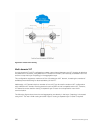
• VLT domain
– A VLT domain supports two chassis members, which appear as a single logical device to network
access devices connected to VLT ports through a port channel.
962
Virtual Link Trunking (VLT)