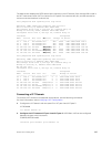
The bold section displays the RSTP state of port channels in the VLT domain. Port channel 100 is used in
the VLT interconnect trunk (VLTi) to connect to VLT peer2. Port channels 110, 111, and 120 are used to
connect to access switches or servers (vlt).
Dell_VLTpeer1# show spanning-tree rstp brief
Executing IEEE compatible Spanning Tree Protocol
Root ID Priority 0, Address 0001.e88a.dff8
Root Bridge hello time 2, max age 20, forward delay 15
Bridge ID Priority 4096, Address 0001.e88a.d656
Configured hello time 2, max age 20, forward delay 15
Interface Designated
Name PortID Prio Cost
Sts Cost Bridge ID PortID
---------- -------- ---- ------- --------- ------- ------------------
Po 1 128.2 128 200000 DIS 800 4096 0001.e88a.d656 128.2
Po 3 128.4 128 200000 DIS 800 4096 0001.e88a.d656 128.4
Po 4 128.5 128 200000 DIS 800 4096 0001.e88a.d656 128.5
Po 100 128.101 128 800 FWD(VLTi) 800 0 0001.e88a.dff8 128.101
Po 110 128.111 128 00
FWD(vlt) 800 4096 0001.e88a.d656 128.111
Po 111 128.112 128 200000 DIS(vlt) 800 4096 0001.e88a.d656 128.112
Po 120 128.121 128 2000 FWD(vlt) 800 4096 0001.e88a.d656 128.121
Dell_VLTpeer2# show spanning-tree rstp brief
Executing IEEE compatible Spanning Tree Protocol
Root ID Priority 0, Address 0001.e88a.dff8
Root Bridge hello time 2, max age 20, forward delay 15
Bridge ID Priority 0, Address 0001.e88a.dff8
We are the root
Configured hello time 2, max age 20, forward delay 15
Interface Designated
Name PortID Prio Cost Sts Cost Bridge ID PortID
---------- -------- ---- ------- -------- - ------- -------------
Po 1 128.2 128 200000 DIS 0 0 0001.e88a.dff8 128.2
Po 3 128.4 128 200000 DIS 0 0 0001.e88a.dff8 128.4
Po 4 128.5 128 200000 DIS 0 0 0001.e88a.dff8 128.5
Po 100 128.101 128 800 FWD(VLTi)0 0 0001.e88a.dff8 128.101
Po 110 128.111 128 00 FWD(vlt) 0 0 0001.e88a.dff8 128.111
Po 111 128.112 128 200000 DIS(vlt) 0 0 0001.e88a.dff8 128.112
Po 120 128.121 128 2000 FWD(vlt) 0 0 0001.e88a.dff8 128.121
Connecting a VLT Domain
To connect a VLT domain to an attached access device, use the following commands.
For more information, refer to Verifying a VLT Configuration.
1. Configure the VLT domain with the same ID in VLT peer 1 and VLT peer 2.
VLT DOMAIN
vlt domain domain id
2. Configure the VLTi between VLT peer 1 and VLT peer 2. LACP/Static LAG can be configured
between the peer units (not shown).
CONFIGURATION mode
interface port-channel port-channel id
Virtual Link Trunking (VLT)
983


