


54 www.emersonct.com SM-EZMotion Module User Guide
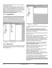
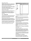
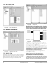
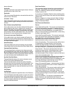
7.4.2 SP I/O Setup View
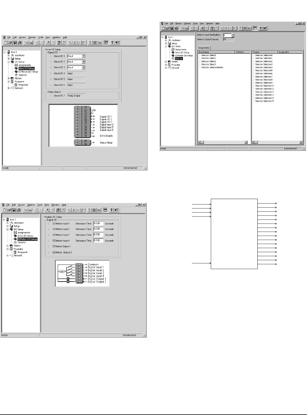
Figure 88: Drive I/O Setup View
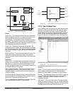
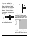
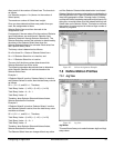
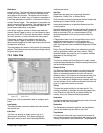
7.4.3 EZ Motion I/O Setup View
Figure 89: Module I/O Setup View
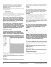
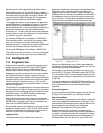
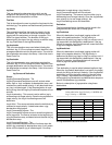
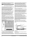
7.4.4 Selector View
The Selector View allows the user to configure the Selector
object. The selector uses a binary to decimal conversion,
which requires fewer I/O points than direct assignments.
Figure 90 shows an example of the Selector view.
Figure 90: Selector View
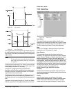
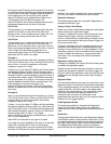
The selector helps to minimize the required number of
inputs and outputs to initiate different actions. The selector
limits the I/O by using a conversion from binary to decimal.
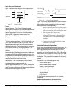
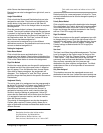
Figure 91 shows a block diagram of the Selector Object.
Figure 91: Selector Block Diagram
The Selector is configured by using a series of Sources
and Destinations on the Assignments view. The inputs to
the selector are Selector.Select# and
Selector.SelectorInitiate. These inputs to the Selector can
be found under the Selector group of Destinations on the
Assignments view. The outputs from the selector are called
Selector.Selection#, and can be found under the Selector
group of Sources on the Assignments view.
In most cases, hardware inputs are assigned to the
Selector.Select functions.
Based on the status of the binary select lines, a
selector.selection source will be active when the
Selector.SelectorInitiate destination is activated.
At the top of the Selector view (see Figure 90), the Selector
Input Destinations field defines how many Select lines will
be used. The number of Selector.Selection outputs is a
Selector.Select0
Selector.Select1
Selector.Select2
Selector.Select3
Selector.Selection0
Selector.Selection1
Selector.Selection2
Selector.Selection3
Selector.Selection4
Selector.Selection5
Selector.Selection6
Selector.Selection7
Selector.Selection8
Selector.Selection9
Selector.Selection1
0
Selector.Selection11
Selector.Selection12
Selector.Selection1
3
Selector.Selection1
4
Selector.Selection1
5
Selector.SelectorInitiate
Selector Object