


28 www.emersonct.com SM-EZMotion Module User Guide
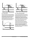
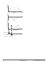
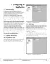
Figure 50: Timed Index Profile
In some cases, an index time is calculated based on other
parameters in a user program. To avoid possible machine
damage, the user can specify maximum values for accel,
velocity, and decel. Therefore, when the SM-EZMotion
firmware calculates accel, velocity, decel, they will never
exceed the maximum values specified by the user, In this
case, where the calculation is limited by a maximum value,
the index will not finish in the specified time. If this
happens, a parameter called Index.ProfileLimited will
activate. It will remain active until cleared by the
Index.ResetProfileLimited destination.
5.5 Gear
The Gear motion profile is used to slave the motion of the
motor to the motion of a master axis at a specified ratio.
Gearing is often referred to as "electronic line shafting" or
"electronic gearing". To gear a follower axis to a master
axis, a ratio (called the gear ratio) must be specified. The
Gear Ratio defines the relationship between the master
and follower motion.
The ratio is calculated as follows:
The ratio is the number of follower distance units to move
the motor per master distance unit of travel. Follower
Distance Units are configured on the User Units view.
Master Distance Units are configured on the Master Setup
screen.
The gear ratio can be positive or negative and is a signed
32-bit parameter. The resolution of the parameter is
determined by the number of decimal places configured for
the Master Velocity Units on the Master Setup screen.
By default, gearing does not use acceleration or
deceleration ramps with respect to the master encoder.
This means that once gearing is activated, peak torque is
available to try to achieve the specified gear ratio.
Therefore, if the master axis is in motion when gearing is
activated, the control loop will attempt to achieve the
programmed ratio within one update without programmed
acceleration. Analogously, when gearing is deactivated,
the motor will use peak torque to bring the motor to a stop
without a deceleration ramp.
Acceleration and Deceleration ramps can be enabled by
the user. If enabled, the Accel and Decel ramps are
specified in units of Follower Units / Velocity Time Base /
Acceleration Time Base. Note that this is a Realtime ramp.
Therefore, the time that it takes to reach the programmed
ratio depends on how fast the master is traveling when
gearing is activated.
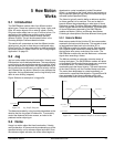
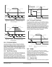
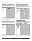
Figure 51 demonstrates that the faster the Master Velocity,
the longer it will take to reach the programmed ratio. If the
Master Axis is not moving when gearing is initiated, then
the follower locks into its programmed gear ratio instantly
(no acceleration time required).
Figure 51: Gear Acceleration Diagram
The GearRatio can be changed on the fly (while gearing is
active and in motion), but acceleration or deceleration must
be enabled to use ramps to achieve the new ratio. If
gearing accel and/or decel ramps are not enabled, the
motor will attempt to achieve the new ratio in one trajectory
update.
5.6 Motion Timebase (Realtime
vs. Synchronized)
The Timebase for a profile determines what parameter is
used as the denominator for velocity and acceleration
units. The default Timebase for all motion types (other than
gear) is Realtime.
A Timebase of Realtime specifies that the denominator for
velocity and acceleration units are units of actual time:
Minutes, Seconds, or Milliseconds (defined on the User
Units View). Therefore, units of velocity for a realtime
Gear Ratio =
# of Follower Distance Units
1 Master Distance Unit
Velocity
Index Accel
2 Seconds
Tim
e
T
1
Programmed
Gear Accel Rate
T
2
T
3
MV
3
MV
2
MV
1
Velocity
Tim
e
T < T < T = The greater the master velocity (MV) the
lon
g
er it takes to accelerate to the Gear Ratio.
123
Gear
Initiate