


How I/O Works www.emersonct.com 31
6 How I/O Works
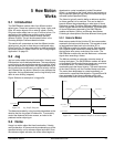
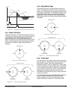
6.1 I/O Scan
When used to activate SM-EZMotion functions, the
Unidrive SP and SM-EZMotion module I/O are scanned
every trajectory update. If the Unidrive SP I/O is used to
trigger functions in the base drive itself (i.e. Threshold
Detectors, Programmable Logic, Binary Sum, etc.), then
the Unidrive SP I/O is only scanned every 4ms. The scan
rate is different when the Unidrive SP I/O is used with
SM-EZMotion functions because the SM-EZMotion
processor scans the I/O faster than the base drive firmware
does.
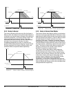
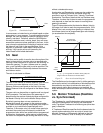
6.2 SM-EZMotion Module I/O
There are four digital inputs and two digital outputs on the
SM-EZMotion module. These I/O are scanned normally at
the trajectory update rate (user configured). If an input is
assigned to a function that does not use captured data,
then it will be updated every trajectory update.
The SM-EZMotion module I/O can also be captured with 1
microsecond accuracy by using the High Speed Capture
object in the SM-EZMotion module. If an input is assigned
to a function that uses captured data (i.e. Index.#.Initiate),
then the input will automatically be captured with 1
microsecond accuracy, and the data is passed to the
destination.
To use the SM-EZMotion module I/O in the PowerTools
Pro Assignments view, the four Inputs are called EZInput.#
and the two Outputs are called EZOutput.# (where #
represents the specific I/O number)
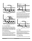
6.3 Unidrive SP I/O
The Unidrive SP has three I/O points that are configured by
the user to be Inputs or Outputs, along with three dedicated
Inputs. The scan rate of the I/O on the Unidrive SP
depends on what they are being used for. If the I/O are
being used by the SM-EZMotion module functions, then
they are updated every trajectory update (user configured).
If the I/O are being used solely for Unidrive SP functions
(i.e. Threshold Detectors, Programmable Logic, Binary
Sum, etc.), then they are updated every 4 milliseconds.
To use the Unidrive SP I/O in the PowerTools Pro
Assignments view, the three Input/Output lines are called
SPIO.#.In or SPIO.#.Out depending on how they are
configured (where # represents the specific I/O number).
The configured Input/Output lines will be listed both on the
Inputs group of Sources, and the Outputs group of
Destinations. Therefore, it is important for the user to know
how the Inputs/Outputs have been configured. The
dedicated Inputs are referred to as SPInput.# (where #
represents the specific I/O number).
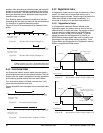
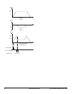
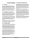
6.4 SM-I/O Plus Module I/O
The SM-I/O Plus module has three I/O points that are
configured by the user to be Inputs or Outputs, along with
three dedicated Inputs. The scan rate of the I/O on the
SM-I/O Plus module depends on how many SM-I/O Plus
modules are being used. If using one SM-I/O Plus module,
the I/O on the SM-I/O Plus module is updated every 8
milliseconds. If a second SM-I/O Plus module is used, the
I/O on both SM-I/O Plus modules are updated every 16
milliseconds.
To use the Unidrive SP I/O in the PowerTools Pro
Assignments view, the three Input/Output lines are called
SlotX.IO.#.In or SlotX.IO.#.Out depending on how they are
configured (where X represents the slot number the
module is located in, and # represents the specific I/O
number). The configured Input/Output lines will be listed
both under the Inputs group of Sources, and the Outputs
group of Destinations. Therefore, it is important for the user
to know how the Inputs/Outputs have been configured. The
dedicated Inputs are referred to as SlotX.Input.# (where X
represents the slot number the module is located in, and #
represents the specific I/O number).
Because of the slower scan rate of the SM-I/O Plus module
inputs and outputs, it is recommended that these I/O not be
used for critical motion functions (e.g. Home Switches,
Registration Sensors, Travel Limits, PLS’s, etc.).