SJ300 Inverter
ix
General Warnings and Cautions
WARNING: Never modify the unit. Otherwise, there is a danger of electric shock and/or
injury.
CAUTION: Withstand voltage tests and insulation resistance tests (HIPOT) are executed
before the units are shipped, so there is no need to conduct these tests before operation.
CAUTION: Do not attach or remove wiring or connectors when power is applied. Also, do not
check signals during operation.
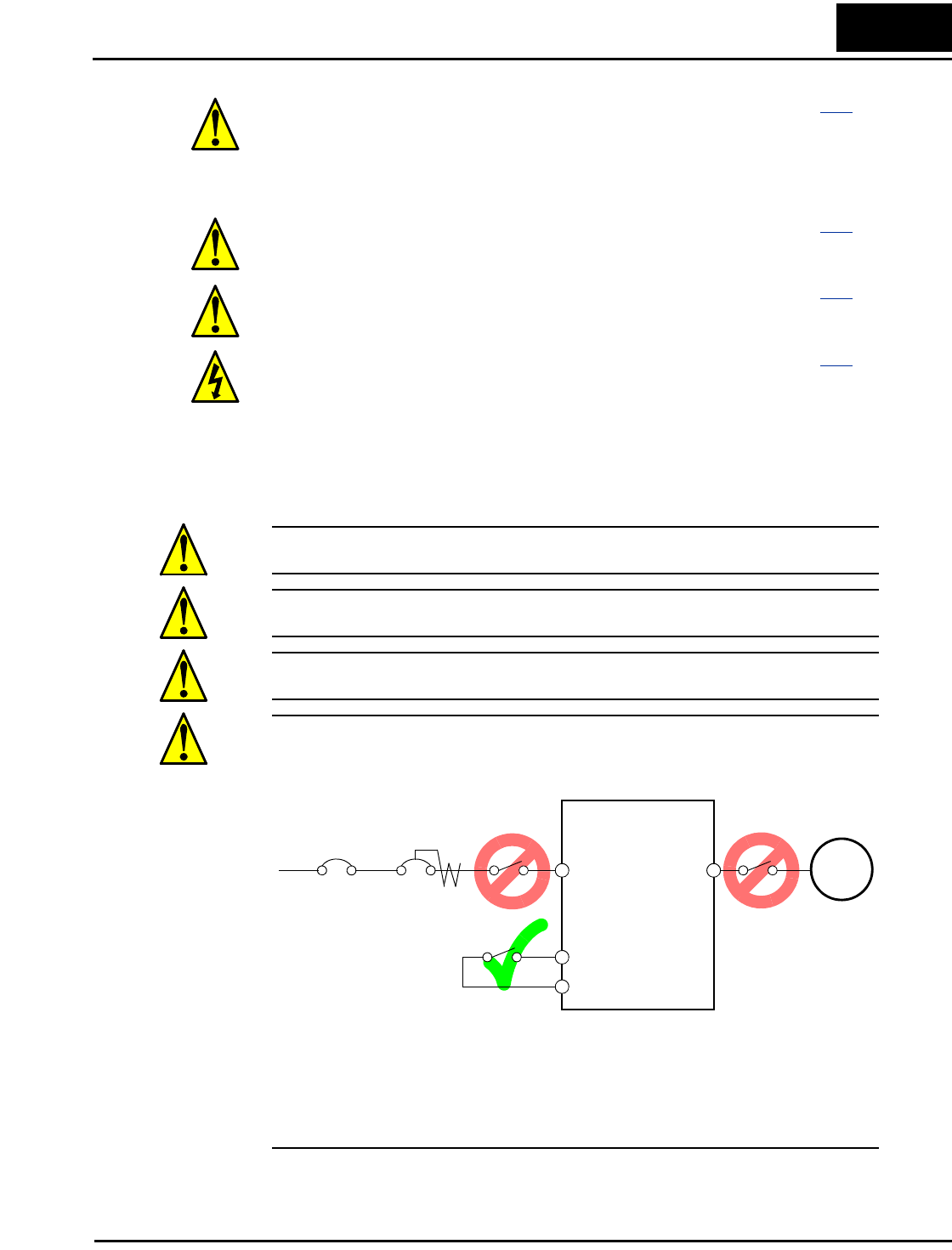
CAUTION: Do not stop operation by switching OFF electromagnetic contactors on the
primary or secondary sides of the inverter.
When there has been a sudden power failure while a Run command is active, then the unit may
restart operation automatically after the power failure has ended. If there is a possibility that
such an occurrence may harm humans, then install an electromagnetic contactor on the power
supply side, so that the circuit does not allow automatic restarting after the power supply recov-
ers. If an optional remote operator is used and the retry function has been selected, this will also
allow automatic restarting when a Run command is active. So, please be careful.
WARNING: The screws that retain the capacitor bank assembly are part of
the electrical circuit of the high-voltage internal DC bus. Be sure that all
power has been disconnected from the inverter, and that you have waited at
least 5 minutes before accessing the terminals or screws. Be sure the charge
lamp is extinguished. Otherwise, there is the danger of electrocution to
personnel.
............. 6–13
CAUTION: Do not operate the inverter unless you have replaced the two
screws that connect the capacitor bank assembly to the internal DC bus.
Otherwise, damage to the inverter may occur.
............. 6–13
CAUTION: Remove the fan assembly carefully, since it is attached to the
unit via connecting wires.
............. 6–14
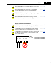
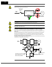
HIGH VOLTAGE: Be careful not to touch wiring or connector terminals
when working with the inverters and taking measurements. Be sure to place
the measurement circuitry above in an insulated housing before using them.
............. 6–16
Power
Input
Inverter
R, S, T
Ground fault
interrupter
U, V, W
Motor
FW
MCCB GFI
L1, L2, L3


