


“A” Group: Standard Functions
Configuring Drive
Parameters
3–16
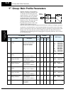
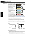
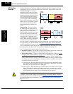
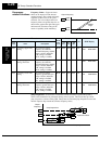
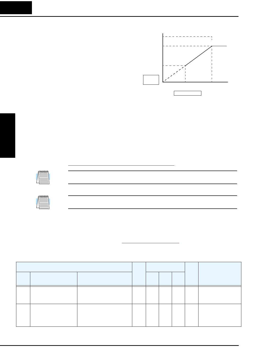
The V/f free-setting endpoint f7/V7
parameters must stay within the more
basic inverter limits in order for the
specified free-setting characteristic
curve to be achieved. For example, the
inverter cannot output a higher voltage
than the input voltage or the AVR
setting voltage (Automatic Voltage
Regulation), set by parameter A082.
The graph to the right shows how the
inverter input voltage would clip (limit)
the characteristic curve if exceeded.
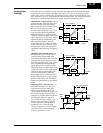
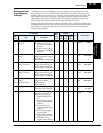
Sensorless Vector Control and, Sensorless Vector Control, 0Hz Domain – These advanced
torque control algorithms improve the torque performance at very low speeds:
• Sensorless Vector Control – improved torque control at output frequencies down to 0.5 Hz
• Sensorless Vector Control, 0Hz Domain – improved torque control at output frequencies
from 0 to 2.5 Hz.
These low-speed torque control algorithms must be tuned to match the characteristics of the
particular motor connected to your inverter. Simply using the default motor parameters in the
inverter will not work satisfactorily for these control methods. Chapter 4 discusses motor/
inverter size selection and how to set the motor parameters either manually or by using the
built-in auto-tuning. Before using the sensorless vector control methods, please refer to
“
Setting Motor Constants for Vector Control” on page 4–65.
NOTE: When the inverter is in SLV (sensorless vector) mode, use B083 to set the carrier
frequency greater than 2.1 kHz for proper operation.
NOTE: You must disable sensorless vector operation when two or more motors are connected
(parallel operation) to the inverter.
Vector Control with Encoder Feedback – This method of torque control uses an encoder as a
motor shaft position sensor. Accurate position feedback allows the inverter to close the velocity
loop and provide very accurate speed control, even with variations in motor loads. To use
encoder feedback you will need to add an SJ–FB Encoder Feedback Card in the inverter’s
expansion bay. Please refer to “
Expansion Cards” on page 5–5 in this manual or the SJ–FB
manual for details.
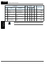
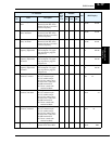
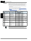
The following table shows the methods of torque control selection.
Output voltage
Output
frequency
(even)
B101 to
B113
(odd)
Voltage to output or AVR voltage
B100 to B112
V7
V6
0
f6 f7 Hz
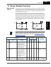
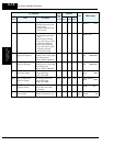
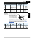
“A” Function
Run
Mode
Edit
Lo Hi
Defaults
Units
SRW Display
Func.
Code
Name Description
–FE
(EU)
–FU
(US)
–FR
(JP)
A041 Torque boost method
selection
Two options:
00 Manual torque boost
01 Automatic torque boost
✘ ✘ 00 00 00 —
>A041 V-Boost
Mode MANUAL
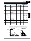
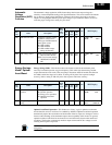
A241 Torque boost method
selection, 2nd motor
Two options (for 2nd
motor):
00 Manual torque boost
01 Automatic torque boost
✘ ✘ 00 00 00 —
>A241 2V-Boost
Mode MANUAL