


SJ300 Inverter
Operations
and Monitoring
4–9
Specifications of
Control and Logic
Connections
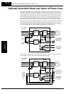
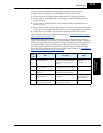
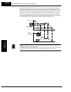
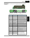
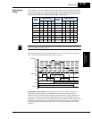
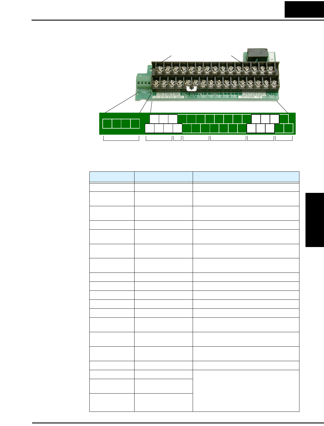
The control logic connector board is removable for wiring convenience as shown below (first,
remove two retaining screws). The small connector to the left is for serial communications.
Specifications for the logic connection terminals are in the following table:
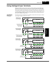
Alarm
relay
Logic
inputs
Analog
inputs
Analog
outputs
Logic
outputs
H O2
CM2
135 3 1 14
7 6 4 2 15
AL1
AL0 AL2
11
12
8
FM
AM
O OIL
SP SN RP SN
PowerSerial
communications
FW
TH
PLC
CM1
P24
CM1
AMI
Retaining screw locations
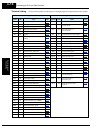
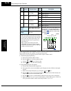
Terminal Name Description Ratings and Notes
[P24] +24V power for inputs 24VDC supply, 100 mA max.
[CM1] +24V common Common for 24V supply, [FW], [TH], inputs [1] to
[8], and [FM]. (Note: Do not ground)
[PLC] Common for logic inputs Common for input terminals [1] to [8], jumper to
CM1 for sinking, jumper to P24 for sourcing
[CM2] Common for logic outputs Common for output terminals [11] to [15]
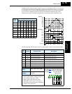
[1], [2], [3], [4], [5],
[6], [7], [8]
Intelligent (programmable)
discrete logic inputs
27VDC max. (use [P24] or an external supply refer-
enced to terminal [CM1]), 4.7kΩ input impedance
[FW] Forward/stop command 27VDC max. (use [P24] or an external supply refer-
enced to terminal [CM1]), 4.7kΩ input impedance
[11], [12], [13],
[14], [15]
Intelligent (programmable)
discrete logic outputs
Open collector type, 50mA max. ON state current,
27 VDC maximum OFF state voltage
[TH] Thermistor input Reference to [CM1], min. thermistor power 100mW
[FM] PWM output 0 to 10VDC, 1.2 mA max., 50% duty cycle
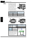
[AM] Voltage analog output 0 to 10VDC, 2 mA max.
[AMI] Current analog output 4-20 mA, nominal load impedance 250Ω
[L] Common for analog inputs Sum of [OI], [O], and [H] currents (return)
[OI] Analog input, current 4 to 19.6 mA range, 20 mA nominal, 100Ω input
impedance
[O] Analog input, voltage 0 to 9.6 VDC range, 10VDC nominal, 12VDC
max., input impedance 10 kΩ
[O2] Analog input, voltage 2 –9.6 to 9.6 VDC range, ±10VDC nominal, ±12VDC
max., input impedance 10 kΩ
[H] +10V analog reference 10VDC nominal, 10 mA max.
[AL0] Relay common contact Contacts AL0–AL1, maximum loads:
250VAC, 2A; 30VDC, 8A resistive load
250VAC, 0.2A; 30VDC, 0.6A inductive load
Contacts AL0–AL2, maximum loads:
250VAC, 1A; 30VDC 1A max. resistive load
250VAC, 0.2A; 30VDC, 0.2A max. inductive load
Min. loads: 100 VAC, 10mA; 5VDC, 100mA
[AL1] Relay contact, normally
closed
[AL2] Relay contact, normally
open