


Step-by-Step Basic Installation
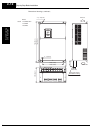
Inverter Mounting
and Installation
2–16
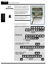
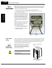
Terminal
Dimensions and
Torque Specs
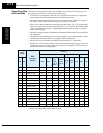
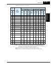
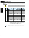
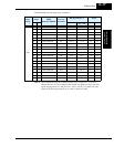
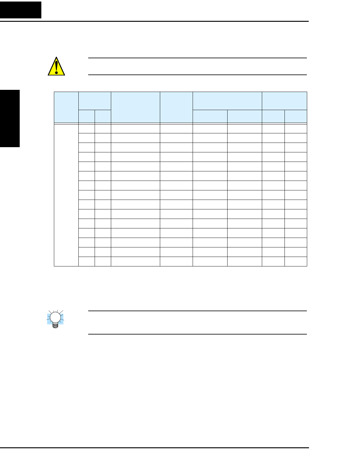
The following tables list the screw size of terminal and recommended torque for tightening for
each of the SJ300 inverter models (400V models are on the next page).
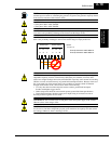
CAUTION: Fasten the screws with the specified fastening torque in the table below. Check for
any loosening of screws. Otherwise, there is the danger of fire.
Note 1: The recommended ring lug connector listing consists of wire size – screw size
format. The wire sizes are in AWG or mm
2
format. For AWG wire sizes, bolt sizes
for the ring lug centers are: #10, #12, 1/4”, 5/16”, and 1/2”. For metric wire sizes,
bolt sizes for the ring lug centers are: 6 = 6M, 8 = 8M, 10 = 10M.
TIP: AWG = American Wire Gauge. Smaller numbers represent increasing wire thickness.
kcmil = 1,000 circular mils, a measure of wire cross-sectional area
mm
2
= square millimeters, a measure of wire cross-sectional area
Input
Volt ag e
Motor
Output
200V
Inverter Models
Screw size
of terminal
Ring lug connector *1 Torque
HP kW (AWG-bolt)
(mm
2
–bolt)
ft-lbs (N-m)
200V
1/2 0.4 SJ300-004LFU M4 20–#10 1.25–4 1.1 1.5
1 0.75 SJ300-007LFU M4 20–#10 1.25–4 1.1 1.5
2 1.5 SJ300-015LFU M4 14–#10 2–4 1.1 1.5
3 2.2 SJ300-022LFU M4 14–#10 2–4 1.1 1.5
5 3.7 SJ300-037LFU M4 10–#10 3.5–4 1.1 1.5
7.5 5.5 SJ300-055LFU M5 8–#12 5.5–5 1.8 2.5
10 7.5 SJ300-075LFU M5 8–#12 8–5 1.8 2.5
15 11 SJ300-110LFU M6 4–1/4 14–6 3.6 4.9
20 15 SJ300-150LFU M6 2–1/4 22–6 3.6 4.9
25 18.5 SJ300-185LFU M6 1–1/4 30–6 3.6 4.9
30 22 SJ300-220LFU M8 1/0–5/16 38–8 6.5 8.8
40 30 SJ300-300LFU M8 2–5/16 60–8 6.5 8.8
50 37 SJ300-370LFU M8 1–5/16 100–8 6.5 8.8
60 45 SJ300-450LFU M10 1/0–1/2 100–10 10.1 13.7
75 55 SJ300-550LFU M10 2/0–1/2 150–10 10.1 13.7