


SJ300 Inverter
Getting Started
1–9
General
Specifications
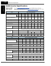
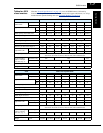
The following table (continued on next page) applies to all SJ300 inverter models.
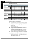
Item General Specifications
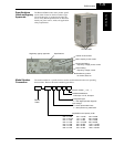
Protective enclosure *1, *11 IP20 (NEMA 1)
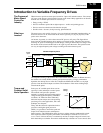
Control method Line-to-line sine wave pulse-width modulation (PWM) control
Output frequency range *4 0.1 to 400 Hz
Frequency accuracy Digital command: ± 0.01% of the maximum frequency
Analog command: ± 0.2% (25°C ± 10°C)
Frequency setting resolution Digital: ± 0.01 Hz; Analog: (max. frequency)/4000, [O] terminal: 12-bit 0 to 10V;
[OI] terminal: 12-bit, 4-20mA; [O2] terminal: 12-bit -10 to +10V
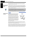
Volt./Freq. characteristic *5 V/F optionally variable (30 to 400Hz base frequency), V/F control (constant torque,
reduced torque), sensorless vector control
Speed fluctuation ± 0.5% (sensorless vector control)
Overload capacity (output current) 150% for 60 seconds, 200% (180% for 75kW / 100HP and larger) for 0.5 seconds
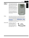
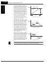
Acceleration/deceleration time 0.01 to 3600 sec., (linear curve profiles, accel./decel. selection), two-stage accel./decel.
Input
signal
Freq.
setting
Operator keypad Up and Down keys / Value settings
Potentiometer Analog setting via potentiometer on operator keypad
External signal *8 0 to 10 VDC (input impedance 10k Ohms), 4 to 20 mA (input impedance 250 Ohms),
Potentiometer (1k to 2k Ohms, 2W)
Serial port RS485 interface
FW/RV
Run
Operator panel Run key / Stop key (change FW/RV by function command)
External signal FW Run/Stop (NO contact), RV set by terminal assignment (NC/NO),
3-wire input available
Intelligent Input
terminals (assign eight
functions to terminals)
RV (reverse run/stop), CF1~CF4 (multi-speed select), JG (jogging), DB (external DC
braking), SET (set 2nd motor data), 2CH (2-stage accel./decel.), FRS (free-run stop),
EXT (external trip), USP (unattended start protection), CS (commercial power source),
SFT (software lock), AT (analog input voltage/current select), SET3 (set 3rd motor
data), RS (reset inverter), STA (start, 3-wire interface), STP (stop, 3-wire interface),
F/R (FW/RV 3-wire interface), PID (PID ON/OFF), PIDC (PID reset), CAS (control
gain setting), UP (remote control Up function, motorized speed pot.), DWN (remote
control Down function, motorized speed pot.), UDC (remote control data clearing),
OPE (Operator control), SF1-SF7 (Multispeed bits 0-7), OLR (Overload limit change),
TL (torque limit enable), TRQ1 (torque limit selection bit 1, LSB), TRQ2 (torque limit
selection bit 2, MSB), PPI (Proportional / Proportional/Integral mode selection), BOK
(Brake confirmation signal), ORT (Orientation – home search), LAC (LAC: LAD
cancel), PCLR (Position deviation reset), STAT (pulse train position command input
enable), NO (not selected)
Thermistor input One terminal (PTC characteristics)
Output
signal
Intelligent Output terminals
(assign six functions to five
open collector outputs and
one relay NO-NC contact)
RUN (run signal), FA1 (Frequency arrival type 1 – constant speed), FA2 (Frequency
arrival type 2 – over-frequency), OL (overload advance notice signal 1), OD (Output
deviation for PID control), AL (alarm signal), FA3 (Frequency arrival type 3 – at-
frequency), OTQ (over-torque signal), IP (Instantaneous power failure signal), UV
(Under-voltage signal), TRQ (In torque limit), RNT (Run time over), ONT (Power-ON
time over), THM (thermal alarm), BRK (Brake release signal), BER (Brake error
signal), ZS (Zero speed detect), DSE (speed deviation maximum), POK (Positioning
completion), FA4 (Frequency arrival type 4 – over-frequency 2), FA5 (Frequency arrival
type 5 – at-frequency 2), OL2 (Overload notice advance signal 2), Terminals 11-13 or
11-14 automatically configured as AC0-AC2 or AC0-AC3 per alarm code output selec-
tion)
Intelligent monitor output
terminals
Analog voltage monitor, analog current monitor (8-bit resolution), and PWM output, on
terminals [AM], [AMI], [FM]
Display monitor Output frequency, output current, motor torque, scaled value of output frequency, trip
history, I/O terminal condition, input power, output voltage