


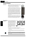
Dynamic Braking
Motor Control
Accessories
5–10
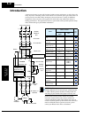
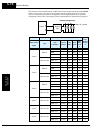
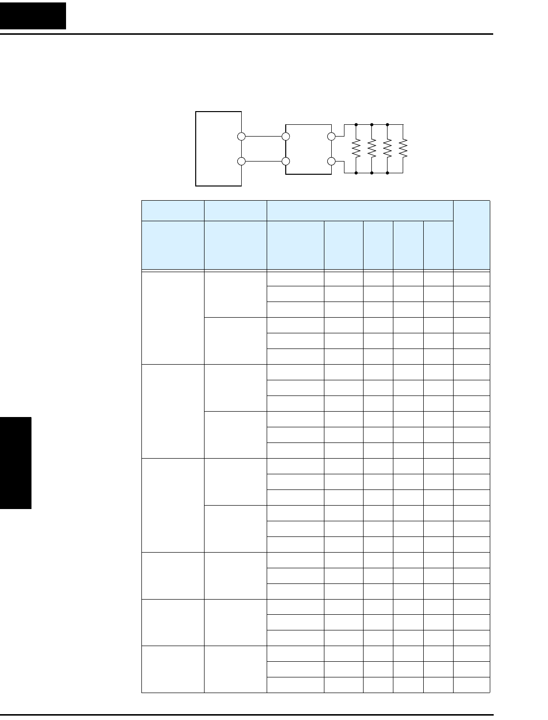
The table below lists the performance of 200V-class inverter models with the optional external
braking units. In some cases, the resistor selection specifies multiple resistors in a parallel,
series, or combination parallel/series configuration. The example diagram shows a parallel
configuration. Please refer to the braking resistor documentation for detailed wiring diagrams.
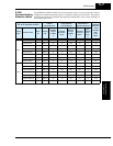
200V Class
Braking Unit Dynamic Braking Resistor Selection
Max.
Braking
Torque,
%
Model Number
SJ300
Type
Type
x (quantity)
Series or
Parallel
Total
Ohms
Total
Watts
Max.
Duty
Cycle,
%
–150LFU
BRD–E2
HRB1 — 50 400 10 30
HRB2 — 35 600 10 35
HRB3 — 17 1200 10 60
BRD–E2–30K
HRB3 x (2) parallel 8.5 2400 20 110
HRB3 x (3) parallel 5.7 3600 20 150
HRB3 x (4) parallel 4.3 4800 20 200
–185LFU
BRD–E2
HRB1 — 50 400 10 25
HRB2 — 35 600 10 30
HRB3 — 17 1200 10 50
BRD–E2–30K
HRB3 x (2) parallel 8.5 2400 20 90
HRB3 x (3) parallel 5.7 3600 20 130
HRB3 x (4) parallel 4.3 4800 20 170
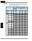
–220LFU
BRD–E2
HRB1 — 50 400 10 25
HRB2 — 35 600 10 30
HRB3 — 17 1200 10 45
BRD–E2–30K
HRB3 x (2) parallel 8.5 2400 20 80
HRB3 x (3) parallel 5.7 3600 20 110
HRB3 x (4) parallel 4.3 4800 20 150
–300LFU BRD–E2–30K
HRB3 x (2) parallel 8.5 2400 20 55
HRB3 x (3) parallel 5.7 3600 20 80
HRB3 x (4) parallel 4.3 4800 20 110
–370LFU BRD–E2–30K
HRB3 x (2) parallel 8.5 2400 20 45
HRB3 x (3) parallel 5.7 3600 20 65
HRB3 x (4) parallel 4.3 4800 20 90
–450LFU BRD–E2–30K
HRB3 x (2) parallel 8.5 2400 20 35
HRB3 x (3) parallel 5.7 3600 20 50
HRB3 x (4) parallel 4.3 4800 20 75
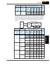
Braking
Unit
Inverter
Example configuration
HRB3 x (4) parallel