


Connecting to PLCs and Other Devices
Operations
and Monitoring
4–8
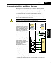
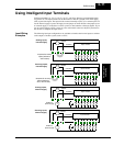
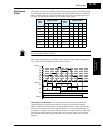
Example Wiring
Diagram
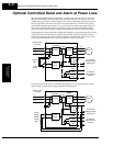
The schematic diagram below provides a general example of logic connector wiring, in
addition to basic power and motor wiring covered in Chapter 2. The goal of this chapter is to
help you determine the proper connections for the various terminals shown below for your
specific application needs.
U
V
W
Motor
R
S
T
Expansion
Card #1
(optional)
Expansion
Card #2
(optional)
T
R
R0
T0
Power source,
3-phase
P24
PLC
FW
8
3
2
1
Forward
Reverse
Intelligent inputs,
8 terminals
CM1
24VDC
TH
FM output
monitor
Thermistor
H
O
O2
OI
L
AM
AMI
4 – 20mA
Analog GND
+
–
+
–
-10 / 0 / +10 VDC
0 – 10VDC
+
–
+10VDC
reference
100Ω
10kΩ
10kΩ
+10VDC reference
P
PD
RB
N
Braking
resistor
(optional)
SP
SN
RP
SN
RS-485 serial
communications
Jumper for
termination
Send/
receive
100Ω
Intelligent relay output
(alarm function default)
Signals for expanded
features, including
encoder feedback,
digital I/O, and
DeviceNet networking
Intelligent outputs,
5 terminals,
open-collector
CM2
11
12
13
14
15
Input
circuits
Output
circuits
FM
Braking
unit
(optional)
AM output
monitor
AMI output
monitor
Control
circuit
Recti-
fier
InverterConverter
DC bus
+
–
+
–
2-wire jumper
J51
Ferrite filter
SJ300
AL0
AL2
AL1
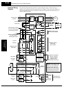
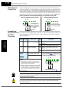
NOTE: For the wiring of intel-
ligent I/O and analog inputs,
be sure to use twisted pair /
shielded cable. Attach the
shield wire for each signal to
its respective common termi-
nal at the inverter end only.
+
–
CM1
Default jumper position
for –xFU/–xFR models
(sourcing type inputs)
Default jumper position
for –xFE models
(sinking type inputs)
L1
L2
L3
T1
T2
T3