


SJ300 Inverter
Operations
and Monitoring
4–5
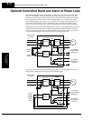
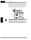
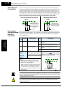
Follow the steps to implement the wiring change shown in the previous diagram.
1. Remove the 2-wire jumper J51 (terminals [R0] and [T0] to connector J51).
2. Procure several inches of multi-strand 20 AWG (0.5mm
2
) or slightly heavier wire.
3. Connect a wire to terminal [R0] that is long enough to connect to terminal [P] (do not
connect to [P] yet).
4. Connect a wire to terminal [T0] that is long enough to connect to terminal [N] (do not
connect to [N] yet).
5. Remove the ferrite filter from the original jumper wire and then slide it onto the new wires
connecting to terminals [R0] and [T0]. (Be sure to save the original jumper in a safe place.)
6. Connect the wire from [R0] to [P], and connect the wire from [T0] to [N] as shown.
More information on power loss related alarm functions, see “
Instantaneous Power Failure /
Under-voltage Signal” on page 4–51.
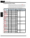
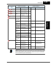
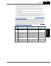
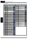
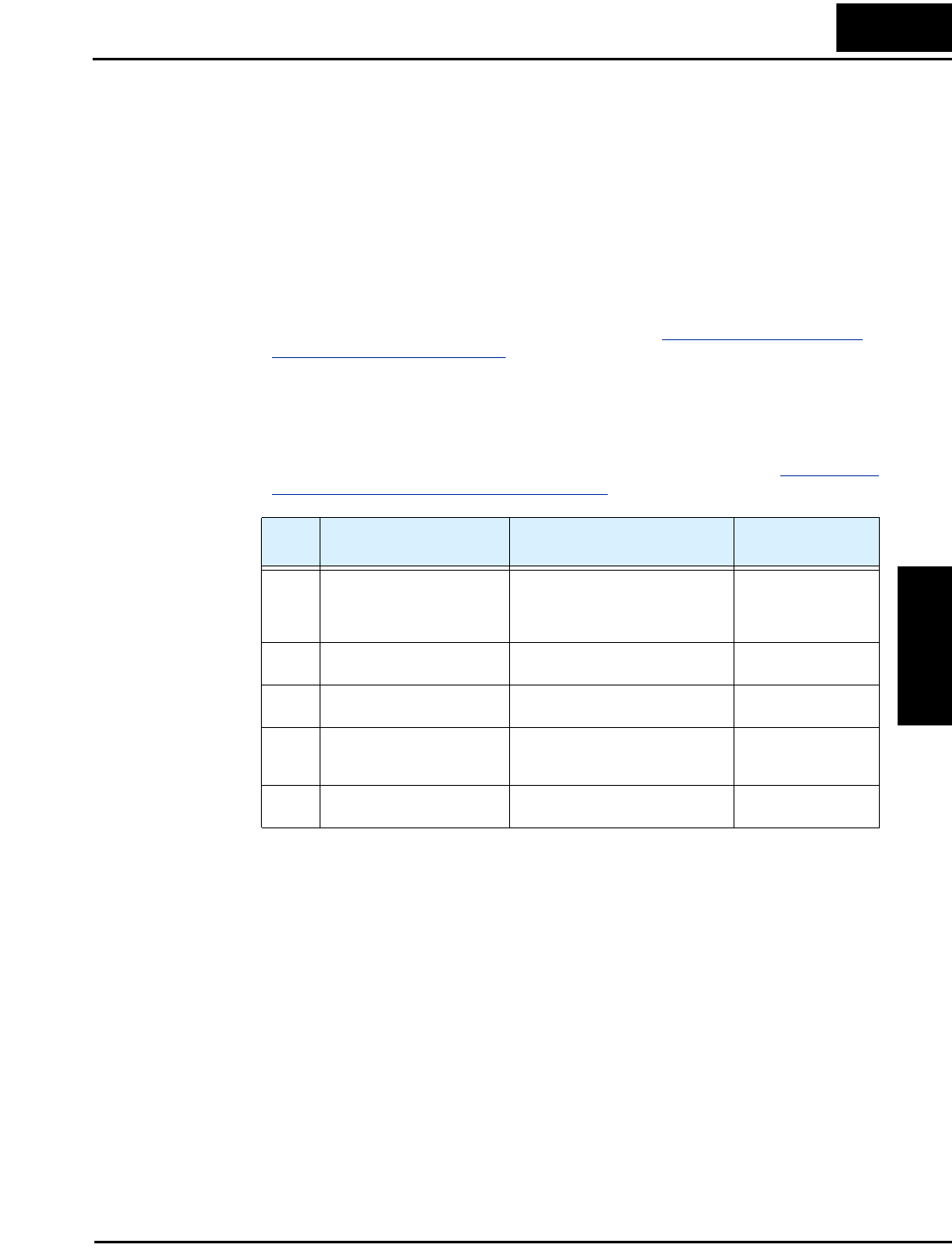
The following table lists the functions related to the controlled deceleration at power loss
feature. After making the wiring change, use function B050 to enable the feature. Use B051 to
determine the point at which a decaying DC bus voltage will trigger the controlled deceleration.
Use parameter B054 to specify an initial step-wise deceleration at power loss, and B053 to
specify the duration of the linear deceleration. Note that this feature also affects the output
signals that indicate instantaneous power fail and under-voltage conditions (see “
Instantaneous
Power Failure / Under-voltage Signal” on page 4–51).
Func.
Code
Name Description Range
B050 Controlled deceleration and
stop on power loss
Allows inverter control using regen-
erative energy to decelerate after loss
of input power (requires jumper
change)
Two option codes:
00Disable
01Enable
B051 DC bus voltage trigger level
during power loss
Sets trigger for controlled decelera-
tion and stop on power loss function
0.0 to 1000.V
B052 Over-voltage threshold during
power loss
Sets over-voltage threshold for
controlled deceleration function
0.0 to 1000.V
B053 Deceleration time setting
during power loss
Deceleration time inverter uses only
at power loss
0.01 to 99.99 sec. /
100.0 to 999.9 sec. /
1000 to 3600 sec.
B054 Initial output frequency
decrease during power loss
Sets the initial decrease in output
frequency upon power loss
0.00 to 10.00 Hz