SJ300 Inverter
Configuring Drive
Parameters
3–15
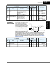
c. After reaching the base frequency, the characteristic maintains a constant output voltage
for higher frequencies.
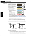
Using parameter A045 you can modify the voltage gain of the inverter. This is specified as a
percentage of the full-scale setting AVR (Automatic Voltage Regulation) in parameter A082.
The gain can be set from 20% to 100%. It must be adjusted in accordance with the motor speci-
fications.
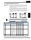
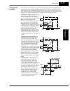
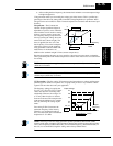
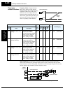
Torque Boost – The Constant and
Variable Torque algorithms feature an
adjustable torque boost curve. When the
motor load has a lot of inertia or starting
friction, you may need to increase the
low frequency starting torque character-
istics by boosting the voltage above the
normal V/f ratio (shown at right). The
boost is applied from zero to 1/2 the
base frequency. You set the breakpoint
of the boost (point A on the graph) by
using parameters A042 and A043. The
manual boost is calculated as an
addition to the standard straight V/f line (constant torque curve).
Be aware that running the motor at a low speed for a long time can cause motor overheating.
This is particularly true when manual torque boost is ON or if the motor relies on a built-in fan
for cooling.
NOTE: Manual torque boost applies only to constant torque (A044=00) and variable torque
(A044=01) V/f control.
NOTE: The motor stabilization parameter H006 is effective for constant torque (A044=00) and
variable torque (A044=01) V/f control.
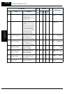
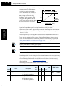
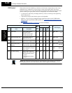
V/f Free-setting – The free-setting V/f inverter mode of operation uses voltage and frequency
parameter pairs to define seven points on a V/f graph. This provides a way to define a multi-
segment V/f curve that best suits your application.
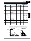
The frequency settings do require that
F1 ≤ F2 ≤ F3 ≤ F4 ≤ F5 ≤ F6 ≤ F7; their
values must have this ascending order
relationship. However, the voltages V1
to V7 may either increase or decrease
from one to the next. The example to the
right shows the definition of a complex
curve by following the setting require-
ments.
Free-setting f7 (B112) becomes the
maximum frequency of the inverter.
Therefore, we recommend setting f7
first, since the initial value of all default
frequencies f1–f7 is 0Hz.
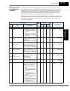
NOTE: The using of V/f free-setting operation specifies parameters that override (make
invalid) certain other parameters. The parameters that become invalid are torque boost (A041/
A241), base frequency (A003/A203/A303), and maximum frequency (A004/A204/A304). In
this case, we recommend leaving their settings at the factory default values.
f base =
60Hz
Torque boost
A042 = 10
A043 = 10%
frequency
100%
10%
0
V
A
6.0Hz 30.0Hz
Output voltage
Output
frequency
(even)
B101 to
B113
(odd)
B100 to B112
V7
V6
V5
V4
V1
V2, V3
0f1f2f3 f4f5f6f7Hz


