


SJ300 Inverter
Operations
and Monitoring
4–19
Two-stage
Acceleration and
Deceleration
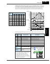
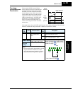
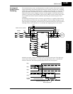
When terminal [2CH] is turned ON, the
inverter changes the rate of acceleration and
deceleration from the initial settings (F002
and F003) to use the second set of accelera-
tion/deceleration values. When the terminal
is turned OFF, the inverter is returned to the
original acceleration and deceleration time
(F002 acceleration time 1, and F003 decel-
eration time 1). Use A092 (acceleration
time 2) and A093 (deceleration time 2) to
set the second stage acceleration and decel-
eration times.
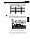
In the graph shown above, the [2CH] signal becomes active during acceleration. This causes the
inverter to switch from using acceleration 1 (F002) to acceleration 2 (A092).
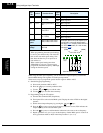
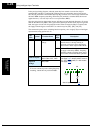
Opt.
Code
Symbol Function Name
Input
State
Description
09 2CH Two-stage Accelera-
tion and Decelera-
tion
ON Frequency output uses 2nd-stage accelera-
tion and deceleration values
OFF Frequency output uses the initial accelera-
tion 1 and deceleration 1 values
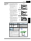
Valid for inputs:
C001, C002, C003, C004,
C005, C006, C007, C008
Required
settings:
A092, A093, A094=0
Notes:
• Function A094 selects the method for second
stage acceleration. It must be set = 00 to
select the input terminal method in order for
the [2CH] terminal assignment to operate.
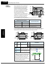
Output
frequency
[FW, RV]
t
target frequency
initial
second
Input
signals
[2CH]
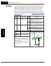
5 3 1
7 6 4 2
8
FW
TH
PLC
CM1
P24
CM1
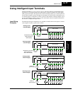
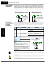
See I/O specs on page 4–9.
Example: (Default input configuration
shown—see page 3–47
. Jumper position
shown is for –xFU/-xFR models; for –xFE
models, see page 4–12
.)
2CH