


Maintenance and Inspection
Troubleshooting
and Maintenance
6–16
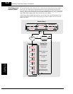
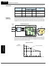
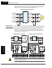
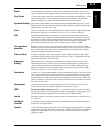
The figure below shows measurement locations for voltage, current, and power measurements
listed in the table on the previous page. The voltage to be measured is the fundamental wave
effective voltage. The power to be measured is the total effective power.
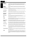
Inverter Output
Voltage Measure-
ment Techniques
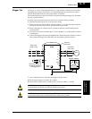
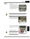
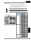
Taking voltage measurements around drives equipment requires the right equipment and a safe
approach. You are working with high voltages and high-frequency switching waveforms that
are not pure sinusoids. Digital voltmeters will not usually produce reliable readings for these
waveforms. And, it is usually risky to connect high voltage signals to oscilloscopes. The
inverter output semiconductors have some leakage, and no-load measurements produce
misleading results. So, we highly recommend using the following circuits to measure voltage
for performing the equipment inspections.
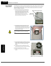
HIGH VOLTAGE: Be careful not to touch wiring or connector terminals when working with
the inverters and taking measurements. Be sure to place the measurement circuitry above in an
insulated housing before using them.
E
1
I
1
I
1
I
1
I
1
E
U-V
E
U-V
E
U-V
W
01
W
02
W
01
W
02
E
1
E
1
I
2
I
3
Three-phase measurement diagram
L1
L2
L3
Inverter
Motor
T1
T2
T3
R
S
T
U
V
W
V/T2
W/T3
U/T1
L2/S
L3/T
L1/R
V/T2
W/T3
U/T1
L2/S
L3/T
L1/R
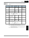
V class Diode bridge Voltmeter
200V class 600V 0.01A min. 300V range
400V class 1000V 0.1 A min. 600V range
220kΩ
2W
+–
220kΩ
2W
+–
Voltage measurement with load
Inverter
Voltage measurement without load
Inverter
V class Diode bridge Voltmeter
200V class 600V 0.01A min. 300V range
400V class 1000V 0.1 A min. 600V range
5kΩ
30W