


SJ300 Inverter
Troubleshooting
and Maintenance
6–17
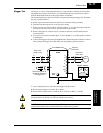
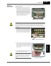
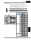
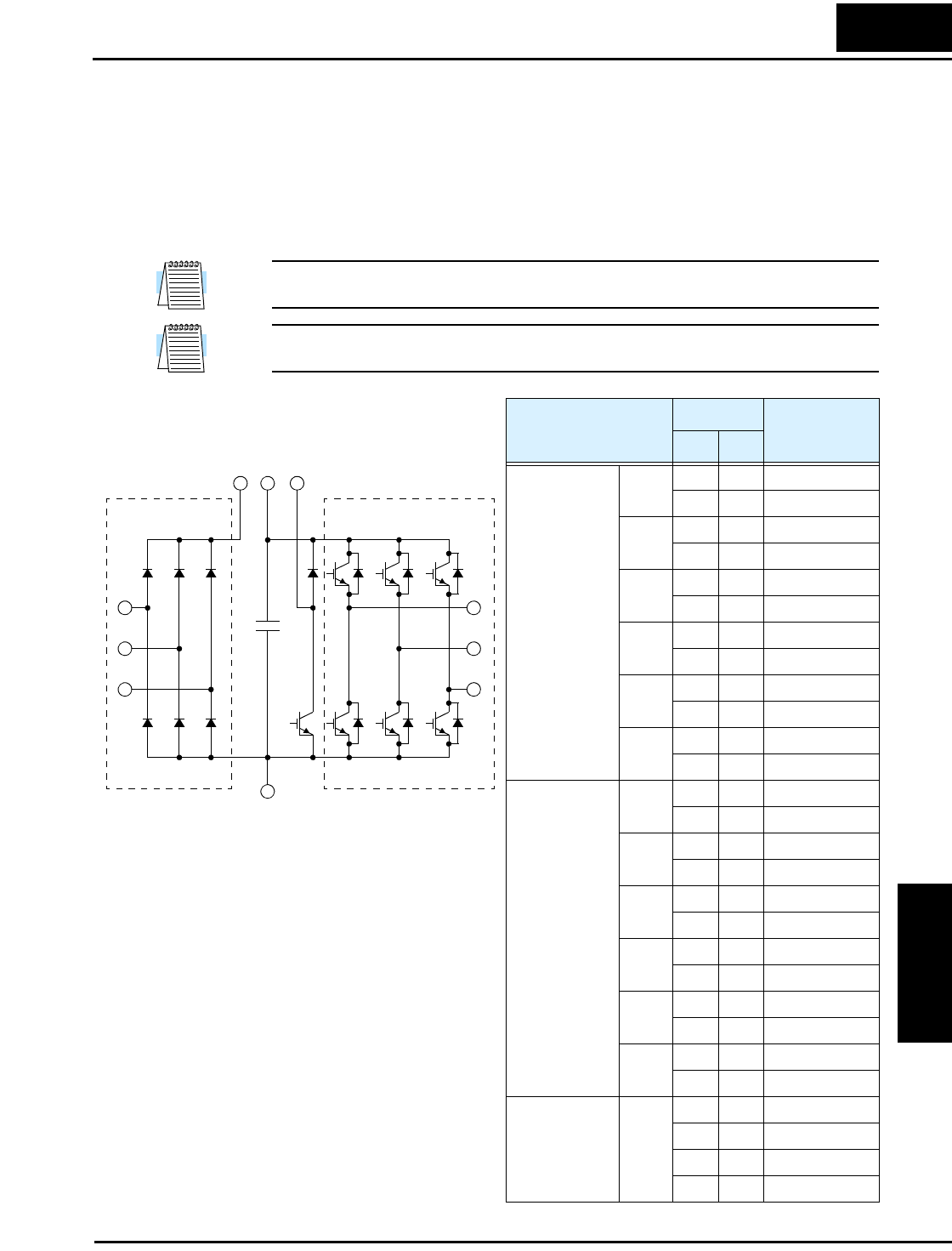
IGBT Test Method The following procedure will check the inverter transistors (IGBTs) and diodes:
1. Disconnect input power to terminals [R, S, and T] and motor terminals [U, V, and W].
2. Disconnect any wires from terminals [P] and [RB] for regenerative braking.
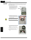
3. Use a Digital Volt Meter (DVM) and set it for 1 ohm resistance range. You can check the
status of the charging state of terminals [R, S, T, U, V, W, RB, P, and N] of the inverter and
the probe of the DVM by measuring the charging state.
Almost infinite ohms = “non-conducting,” and 0 to 10 ohms = “conducting.”
NOTE: The resistance values for the diodes or the transistors will not be exactly the same, but
they will be close. If you find a significance difference, a problem may exist.
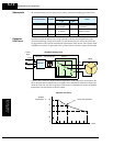
NOTE: Before measuring the voltage between [P] and [N] with the DC current range, confirm
that the smoothing capacitor is discharged fully, then execute the tests.
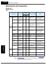
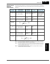
Circuit Type
DVM Probe
Measured Value
+ –
Converter
D1
R PD Non-conducting
PD R Conducting
D2
S PD Non-conducting
PD S Conducting
D3
T PD Non-conducting
PD T Conducting
D4
R N Conducting
N R Non-conducting
D5
S N Conducting
N S Non-conducting
D6
T N Conducting
N T Non-conducting
Inverter
TR1
U P Non-conducting
P U Conducting
TR2
V P Non-conducting
P V Conducting
TR3
W P Non-conducting
P W Conducting
TR4
U N Conducting
N U Non-conducting
TR5
V N Conduct
N V Non-conducting
TR6
W N Conducting
N W Non-conducting
Dynamic
Braking
(0.4kW–11kW)
TR7
RB P Non-conducting
P RB Conducting
RB N Non-conducting
N RB Non-conducting
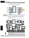
R
S
T
D1 D2 D3
D4 D5 D6
U
V
W
TR1 TR2 TR3
TR4 TR5 TR6
PD PRB
C
TR7
+
Converter Inverter
N