


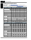
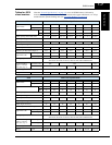
SJ300 Inverter Specifications
Geting Started
1–10
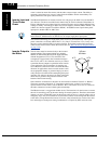
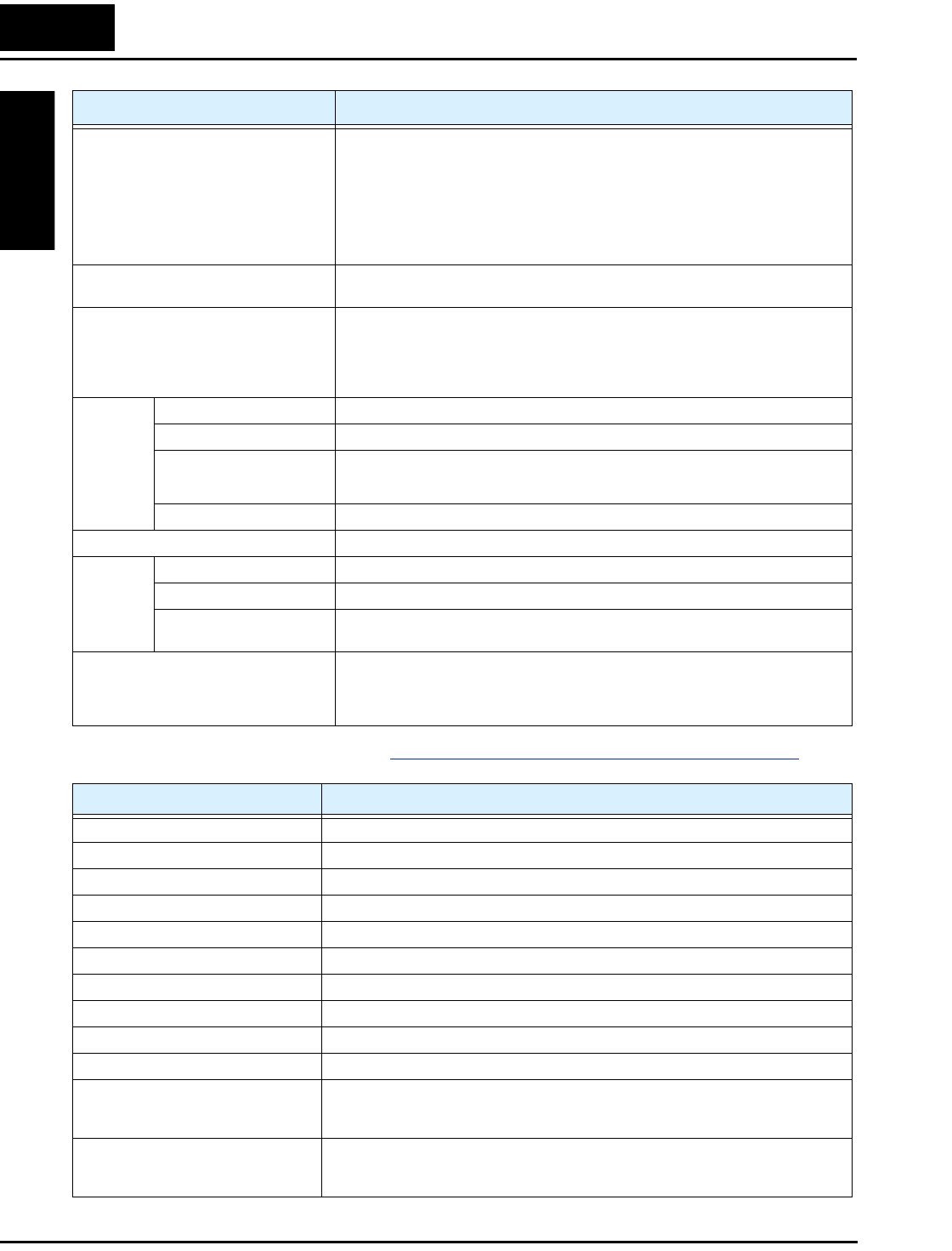
Signal Ratings Detailed ratings are in “Specifications of Control and Logic Connections” on page 4–9.
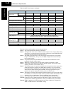
Other user-settable parameters V/F free-setting (up to 7 points), freq. upper/lower limit, freq. jump, accel/decel curve
selection, manual torque boost value and freq. adjustment, analog meter tuning, start
frequency, carrier frequency, electronic thermal protection level, external frequency
output zero/span reference, external frequency input bias start/end, analog input selec-
tion, retry after trip, restart after instantaneous power failure, various signal outputs,
reduced voltage start, overload restriction, default value setting (US, Europe, Japan),
deceleration and stop after power failure, AVR function, fuzzy accel/decel, auto-tuning
(on-line/off-line), high-torque multi-operation, automatic energy-saving operation
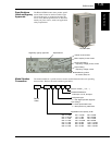
Carrier frequency range Models SJ300–015xxx to 750xxx: 0.5 to 12 kHz
Models SJ300–900Hxx to 1320Hxx: 0.5 to 8 kHz
Protective functions Over-current, overload, braking resistor overload, over voltage, EEPROM error, under-
voltage error, CT (current transformer) error, CPU error, external trip, USP error,
ground fault, input over voltage, instantaneous power failure, expansion card 1 error,
expansion card 2 error, inverter thermal trip, phase failure detection, IGBT error,
thermistor error
Environ-
ment
Temperature (*9) Operating (ambient): -10 to 50°C / Storage: -20 to 65°C
Humidity 20 to 90% humidity (non-condensing)
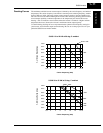
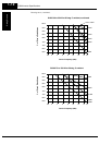
Vibration *10
Models SJ300–004xxx to 220xxx: 5.9 m/s
2
(0.6G), 10 to 55 Hz
Models SJ00–300xx to 1500xxx: 2.94 m/s
2
(0.3G), 10 to 55 Hz
Location Altitude 1,000 m or less, indoors (no corrosive gasses or dust)
Coating color Gray
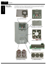
Accessories Feedback PCB SJ-FB (vector control loop speed sensor)
Digital input PCB SJ-DG (4-digit BCD / 16-bit binary)
Others EMI filters, input/output reactors, DC reactors, radio noise filters, braking resistors,
braking units, LCR filter, communication cables, factory I/O network interface cards
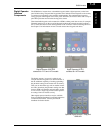
Operator input devices OPE–SRE (4-digit LED with potentiometer) / OPE–S (4-digit LED w/o potentiometer),
Optional: OPE-SR (4-digit LED with potentiometer, Japanese/English overlay),
SRW–0EX Multilingual operator with copy function (English, French, German, Italian,
Spanish, and Portuguese)
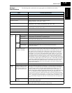
Item General Specifications
Signal / Contact Ratings
Built-in power for inputs 24VDC supply, 100 mA maximum
Intelligent (programmable) logic inputs 27VDC maximum, 4.7kΩ input impedance
Intelligent (programmable) logic outputs Open collector type, 50mA max. ON state current, 27 VDC maximum OFF state voltage
Thermistor input Minimum thermistor power 100mW
PWM output 0 to 10VDC, 1.2 mA max., 50% duty cycle
Voltage analog output 0 to 10VDC, 2 mA max.
Current analog output 4-20 mA, nominal load impedance 250Ω
Analog input, current 4 to 19.6 mA range, 20 mA nominal
Analog input, voltage 0 to 9.6 VDC range, 10VDC nominal, 12VDC max., input impedance 10 kΩ
+10V analog reference 10VDC nominal, 10 mA maximum
Alarm relay, normally closed contacts Maximum loads: 250VAC, 2A; 30VDC, 8A resistive load
250VAC, 0.2A; 30VDC, 0.6A inductive load
Minimum loads: 100 VAC, 10mA; 5VDC, 100mA
Alarm relay, normally open contacts 250VAC, 1A; 30VDC 1A max. resistive load /
250VAC, 0.2A; 30VDC, 0.2A max. inductive load
Min. loads: 100 VAC, 10mA; 5VDC, 100mA